• Do not overtighten the bolts in the Barksdale
height-control valve housing. The bolts should
not be loose, and should not require tightening.
Only if necessary, tighten the valve housing
bolts 45 lbf·in (500 N·cm). Any damage to the
valve housing will void the warranty.
• Do not attempt to disassemble the Barksdale
valve body or the control lever. There are no
serviceable parts in the valve, and any disas-
sembly will void the warranty.
NOTICE
When removing or loosening a Barksdale height-
control valve from a mounting bracket, always
hold the valve-side mounting studs in place with
an Allen wrench while loosening or tightening the
nuts that attach the valve to the bracket. Because
the mounting studs are threaded into the valve
body, loosening the nuts without holding the
studs can tighten the studs, which can crush the
valve body and damage the valve. Conversely,
tightening the nuts without holding the studs can
back the studs out, causing a separation of the
two halves of the valve body, and possibly a leak.
1. Park the vehicle on a level surface, using a light
application of the brakes. Do not apply the park-
ing brakes. Shift the transmission into neutral,
and build the secondary air pressure to at least
100 psi (690 kPa). Shut down the engine.
2. Mark the location of the front and rear tires on
the floor, and chock the tires on one axle only.
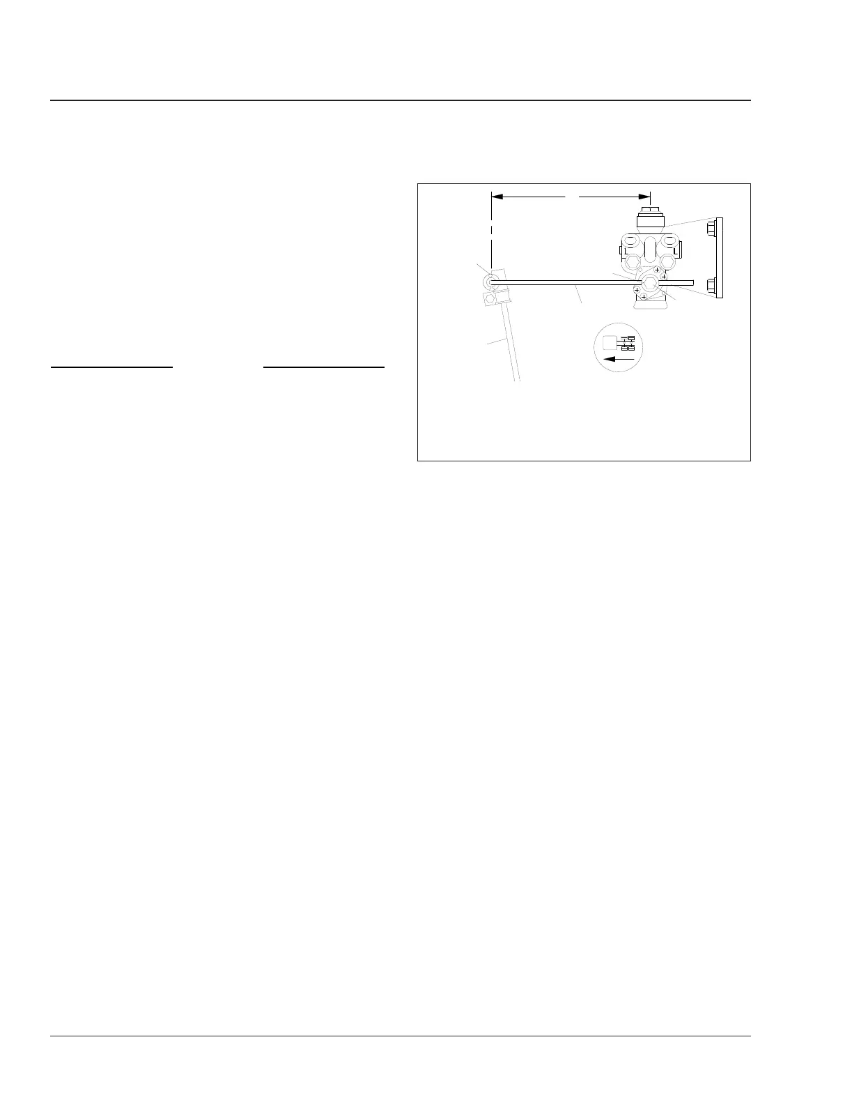
3. Check the length of the overtravel lever between
its pivot points. See
Fig. 6, Ref. A.
3.1 If the vehicle is equipped with an adjust-
able leveling valve, the length should be
8 inches (203 mm). If the length is incor-
rect, see Group 32 of the Century Class
Trucks Workshop Manual for adjustment
procedures.
3.2 If the vehicle is equipped with a fixed lev-
eling valve, see Group 32 of the Century
Class Trucks Workshop Manual for the
overtravel lever length for the rear axle
installed in your vehicle.
4. On single-drive rear axle configurations, measure
the distance from the bottom of the left axle stop
to the top of the U-bolt pad. On tandem (dual-
drive) rear axle configurations, measure the dis-
tance from the bottom of the forwardmost left
axle stop to the top of the axle U-bolt pad. See
Fig. 7, Ref. A. The correct distance for single
and dual-drive rear axles is between 2-3/8 inches
and 2-7/8 inches (60 to 73 mm).
5. If the axle stop measurement is not correct, see
Group 32 of the Century Class Trucks Workshop
Manual for adjustment procedures.
6. Apply the parking brakes, and remove the
chocks.
Chalmers Suspension
1. Chock the front tires then place the transmission
in neutral, and release the parking brakes.
2. Power wash the suspension, or clean it with a
hard-bristle brush before performing a visual in-
spection.
3. Inspect the rubber bushings for cracks or other
damage.
Try to move the torque rod ends using your
hands only, and check for any free-play. If free-
play is felt, replace the torque rod end bushing.
Do not use a pry bar to check for free-play. Use
of a pry bar may lead to premature bushing re-
placement.
4. Lift the rear of the vehicle and support the frame
on jack stands to unload the suspension compo-
3
4
2
A
05/15/95
f320410
1
5
A. Measure the length of the overtravel lever between
these two points.
1. V-Shaped Mark
2. Adjustment Locknut
3. Overtravel Lever
4. Cotter Pin
5. Linkage Rod
Fig. 6, AirLiner Overtravel Lever and Linkage Rod
Measurement
Suspension32
Century Class Trucks Maintenance Manual, January 201632/4
 Loading...