EVT–300 Maintenance and
Diagnostics
1.
Keep the antenna assembly and side sensor(s)
free of a buildup of mud, dirt, ice, or other debris
that might reduce the system’s range.
2.
The system tests itself continuously and evalu-
ates the results every 15 seconds. If a problem
is detected with the front radar system, the red
FAIL light on the DDU illuminates continuously as
long as the failure is active. The corresponding
fault code is stored in the CPU’s memory.
3.
Both active and inactive fault codes can be indi-
cated by the DDU when the system is placed in
failure display mode. Inactive faults are those
that have occurred and have cleared. Active
faults are still present. Fault codes provide the
driver the ability to record the system faults dur-
ing a trip and to notify his/her maintenance de-
partment or Eaton VORAD. See "EVT–300 Fail-
ure Display Mode/Fault Codes" below. In this
mode, specific fault codes are indicated by the
pattern of blinks of the driver display unit red
FAIL light.
4.
Each fault code is a two-digit number, as shown
in Table 2.5. The red FAIL light blinks the same
number of times as the first digit, a pause of ap-
proximately 3/4 of a second follows, then the
light blinks the same number of times as the sec-
ond digit.
5.
Additional fault codes are blinked out at intervals
of approximately eight seconds. After all the fault
codes have been displayed, a code 41 will be
flashed.
EVT–300 Failure Display Mode/Fault
Codes
1.
Press and hold the DDU volume control and
power ON/OFF knob. Continue pressing the
knob until the FAIL light begins to blink in ap-
proximately five seconds. If so configured, the
system will turn off if you release the knob before
five seconds. After five seconds, the DDU FAIL
light begins to blink out the failure flash codes. A
code 41 will be displayed either if no faults are
found or when all fault codes have been dis-
played.
2.
Position the DDU range knob to the left to blink
active fault codes and to the right to blink inac-
tive codes.
3.
Fault codes can only be reviewed, tested, and
cleared by using a Pro-Link
®
9000 diagnostic
tool.
Lane Guidance
™
System,
Optional
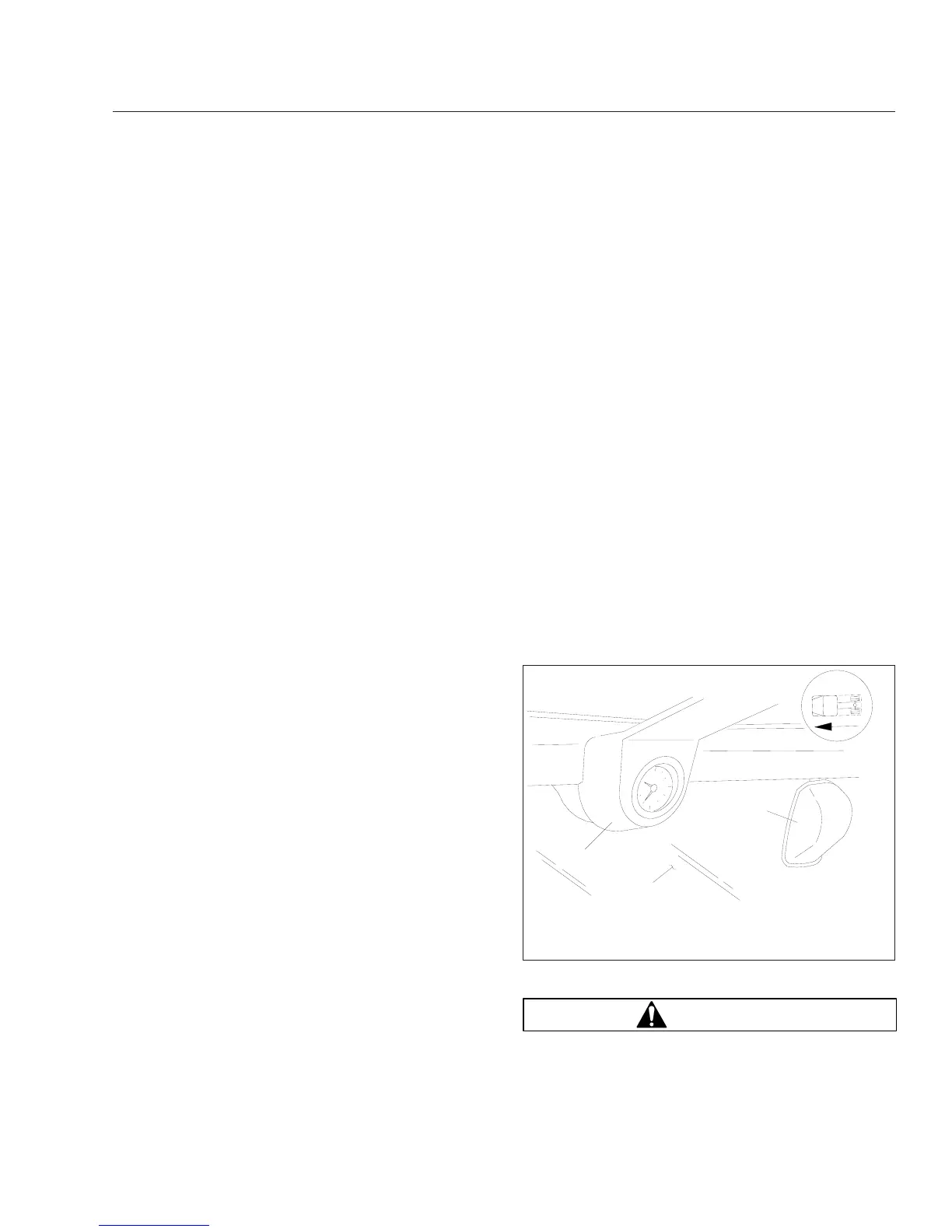
The Lane Guidance lane departure warning system
monitors the vehicle’s position within the roadway
lane markings and sounds a warning in the cab
when the vehicle is about to stray outside its lane,
provided the turn signal is not on and the vehicle is
traveling at least 40 mph (64 km/h). The system in-
cludes a digital camera mounted high near the center
of the windshield inside the cab, a central processing
unit in the overhead console, and a stereo speaker
above and behind each door that emits a sound simi-
lar to a rumble strip. See Fig. 2.47. The sound is
made on the side of the vehicle it’s straying toward,
prompting the driver to respond and steer away from
the sound and back into the center of the correct
lane.
WARNING
The lane departure warning system is intended
only as an aid for a conscientious and alert
11/18/1999
f610358
1
2
3
1. Clock
2. Windshield
3. Digital Camera
Fig. 2.47, Lane Departure Warning System Camera
Instruments and Controls Identification
2.38