the engine is stopped. A completely discharged bat-
tery will produce only about 12.0 volts. The voltmeter
will indicate lower voltage as the vehicle is being
started or when electrical devices in the vehicle are
being used.
If the voltmeter shows an undercharged or over-
charged condition for an extended period, have the
charging system and batteries checked at a repair
facility.
NOTE: Some vehicles may be equipped with a
digital display voltmeter integrated into the mes-
sage display screen, instead of a voltmeter
gauge.
Turbocharger Boost Pressure Gauge,
Optional
A turbocharger boost pressure gauge measures the
pressure in the intake manifold, in excess of atmos-
pheric pressure, being created by the turbocharger.
See Fig. 2.16.
Pyrometer, Optional
A pyrometer registers the exhaust temperature near
the turbocharger. See Fig. 2.16. Normal exhaust
temperatures are listed in Table 2.3.
Variations in engine load can cause exhaust tem-
peratures to vary. If the pyrometer reading shows
that exhaust temperature exceeds normal, reduce
fuel to the engine until the exhaust temperature is
reduced. Shift to a lower gear if the engine is over-
loaded.
Exhaust Temperature
Engine Model
Exhaust Temperature:
°F (°C)
Caterpillar C–10, C–12 935–1290 (500–700)
Caterpillar 3406E 900–1100 (480–595)
Cummins M11 800–1000 (430–540)
Cummins N14 750–950 (400–510)
Detroit Diesel S60 700–950 (370–510)
MBE4000 750–1022 (400–550)
Table 2.3, Typical Pyrometer Exhaust Temperature
Readings
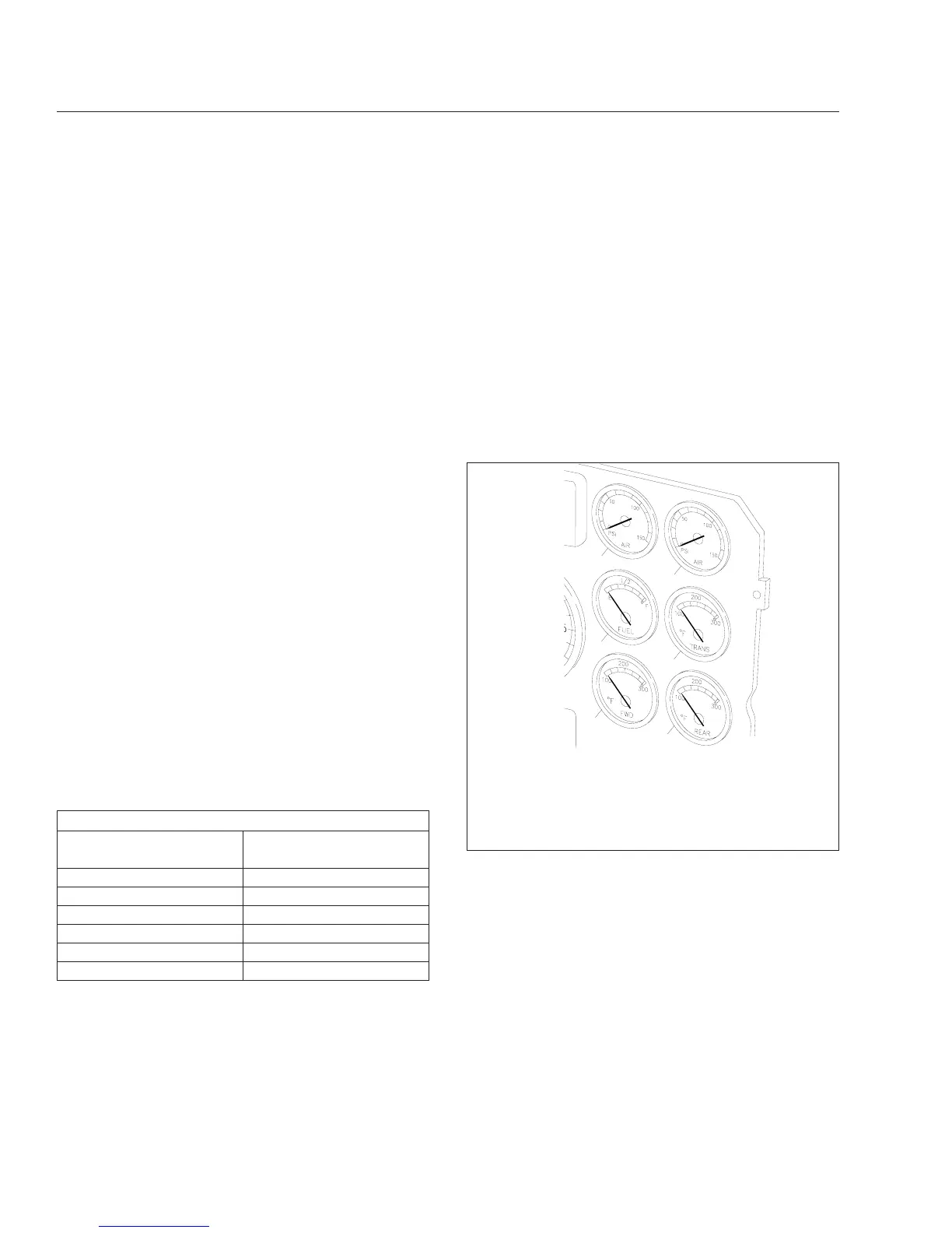
Primary and Secondary Air Pressure
Gauges
Air pressure gauges register the pressure in the pri-
mary and secondary air systems. See Fig. 2.17. Nor-
mal pressure, with the engine running, is 100 to 120
psi (689 to 827 kPa) in both systems. A low-air-
pressure warning light and buzzer, connected to both
the primary and secondary systems, activate when
air pressure in either system drops below a minimum
pressure of 64 to 76 psi (441 to 524 kPa). When the
engine is started, the warning light and buzzer re-
main on until air pressure in both systems exceeds
minimum pressure.
Fuel Gauge
The fuel gauge indicates the level of fuel in the fuel
tank(s). See Fig. 2.17. If equipped with a second
(optional) fuel gauge, each fuel tank level is indicated
on a separate gauge.
Transmission Oil Temperature Gauge,
Optional
During normal operation, the transmission oil tem-
perature gauge reading should not exceed 250°F
f601127
1
2
3
4
5
6
02/12/96
1. Primary Air Pressure Gauge
2. Secondary Air Pressure Gauge
3. Fuel Gauge
4. Transmission Oil Temperature Gauge (optional)
5. Forward Axle Oil Temperature Gauge (optional)
6. Rear Axle Oil Temperature Gauge (optional)
Fig. 2.17, Instrument Panel Gauges (right side)
Instruments and Controls Identification
2.15
 Loading...