FC-302 Data Radio User Manual
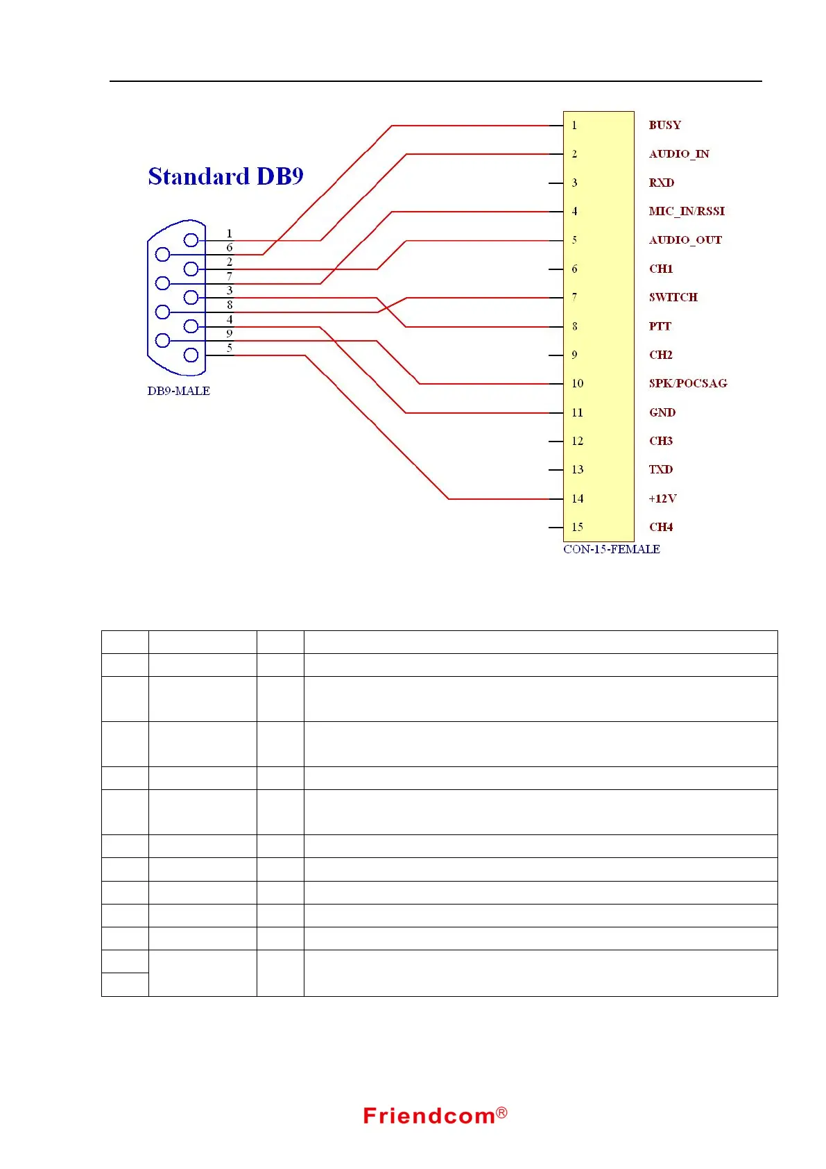
Fig.16 DB9 Interface Pin Assignment
Mainboard connect to modem(J100---J2)
No. Name Type Description
1 GND I/O Ground
2 RFSK O
The output signal after the intermediate frequency demodulation in receiver.
200mVrms,sent to modem
3 TFSK I
Baseband signal input end for the modulation in transmitter, 100mVrms,sent
from modem to mainboard
4 DATA_PTT I Data TX control. Active when low level. Control the mainboard via modem
5 BUSY O
BUSY output. low level when receiving (Default). Sent from mainboard to
modem
6 RSSI O Received field strength output, transferred from mainboard to modem
7 RD I Data communication serial port from modem to mainboard
8 TD O Data communication serial port from mainboard to modem
9 /RESET I Reset control, low level when resetting. Control the mainboard via modem
10 GND I/O GND
11
BASE_5V O
+5V power supply,transferred from mainboard to modem, Maximum current
50mA.
12