117
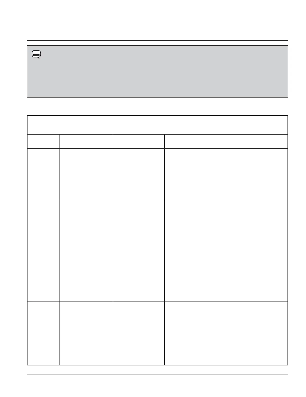
Factory Line-Test Mode
Diagnostic Mode (All Cycle Selector positions in this table are going clockwise from Position-0)
Selector
Position
Encoder Positions
Test/Activated
Components
Operator Check
0 N/A
Status-LEDs/
7- Segment
(select models)/
Beeper Test
Normal Operation: Beeper:1s
on-1s off-Repeats—255 Times**.
LEDs On: Same pattern
as beeper.
1 N/A NTC Test
Check for the following beeper/LED pattern:
A) Normal operation: 3s On-1s Off-1s On-1s
Off-Repeat— 255 Times**.
B) NTC-open: 0.25s On-0.25s
Off- Repeats—255 Times**.
C) NTC-short: 0.25s On-0.25s
Off-0.25s On-3s
Off- Repeats—255 Times**.
2
Temp Selector:
Medium/Normal
Rocker
Switches
(select models): ON
Motor + Heater
Check the Motor and Heater function: LEDs On: Drying
and Cool-Down On.
NOTE
If the Diagnostic Mode cannot be entered even after the correct execution of Steps 1— 4, check the wiring and
the edge connectors, i.e.; J7 (LC-Main Board), J7A (FSD-UI Board), J8 (LC-Main Board), J8A (FSD-UI Board), J10
(LC & FSD-Main Board), J10A (FSD_UI Board) and J9 (FSD-UI Board) and the edge connectors / wiring for the
Dryness encoder and Cycle Selector. If the Diagnostic Mode is still not entered, replace them and retry. If that does
not solve the problem, replace the UI (FSD) and / or Main Board (UI & FSD) and retry.
 Loading...