EasyManua.ls Logo

Fromm A383.0001 - User Manual

Fromm A383.0001
28 pages
Print Icon
To Next Page IconTo Next Page
Loading...
13675001.en/MAS/©09.07
CE Declaration of conformity
We declare that the machine A383
is in conformity with the following standard or
standardised documents:
98/37/EEC
FROMM Holding AG
Hinterbergstrasse 26
CH - 6330 Cham
27.03 2001
R.Fromm
Director
OPERATION MANUAL / SPARE PARTS LIST
PNEUMATIC STEEL
STRAPPING TOOL
MODEL A383.0001
13.6750.01
WWW.TRADITIONALTOOL.COM
For Parts & Service 1-877-862-6699
Question and Answer IconNeed help?

Do you have a question about the Fromm A383.0001 and is the answer not in the manual?

Summary

Safety Instructions and Hazards

Eye Injury Prevention

Importance of wearing safety glasses with side shields for eye protection.

Operational Safety Precautions

Guidelines for safe operation, handling, and avoiding pinch/cut hazards.

Strap Handling and Breakage Risks

Warnings regarding strap dispensing, cutting tensioned straps, and strap breakage hazards.

Workspace Safety and Tool Condition

Maintaining tidy workspace, good balance, and tool condition for accident prevention.

Warranty and Product Use

Warranty Conditions and Exclusions

Details the warranty period, coverage, and exclusions for the strapping tool.

Intended Use of the Tool

Specifies that the tool is designed exclusively for steel strapping packages.

Tool Model Chart

Technical Data and Specifications

Physical Dimensions and Weight

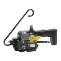
Provides physical dimensions and weight of the strapping tool.

Sound and Vibration Information

Details sound pressure level and vibration acceleration values.

Compressed Air and Strap Requirements

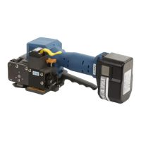
Specifies air connection, consumption, and suitable steel strap types.

Installation and Setup

Compressed Air Connection Guide

Instructions for connecting compressed air supply to the tool.

Suspension of the Tool

Explains how to suspend the tool using available brackets and balancers.

Operating Controls Identification

Tool Operation Procedures

Feeding Strap Around Package

Step-by-step guide on how to feed the strap around the package.

Loading Strap into the Tool

Instructions for correctly inserting the strap into the tool mechanism.

Tensioning the Strap

Procedure for tensioning the strap using the tool's levers.

Sealing the Strap

Steps for performing the sealing operation on the strap.

Removing Tool After Sealing

How to safely detach the tool from the tensioned and sealed strap.

Seal Quality Verification

Correct Seal Identification

Criteria for a properly formed seal, including depth and shearing.

Incorrect Seal Diagnosis

How to identify seals with incorrect depth or damage, indicating adjustment needs.

Seal Adjustment Guide

Adjusting Sealing Depth

Instructions for adjusting the sealing depth to correct excessive or insufficient sealing.

Maintenance and Care

Air Unit Maintenance

Daily checks for air pressure and oil level in the air-unit separator and filter.

Pressure Intensifier Oil Level Check

How to check and refill oil in the pressure intensifier for optimal tool function.

Cleaning and Lubrication Procedures

Guidelines for cleaning the feed wheel and lubricating moving parts.

Wearing Parts Replacement Guide

Punch and Die Halves Replacement

Procedure for replacing worn punch and die components.

Feed Wheel Replacement

Steps to replace the feed wheel assembly.

Gripper Replacement Procedure

Instructions for removing and installing a new gripper.

Cutter Replacement Instructions

Method for removing and replacing the tool's cutter component.

Control System Diagrams

Pneumatic Schematic Overview

Visual representation of the tool's pneumatic control system with component numbering.

Detailed Control System Components

Detailed illustrations and descriptions of the pneumatic control system parts.

Functional Operation Stages

Idle Position and Strap Insertion

Description of the tool's state when idle and the process of inserting the strap.

Strap Tensioning Process

Explanation of how the tool tensions the strap, including air motor operation.

Sealing Mechanism Action

How the sealing process is initiated and executed, including hydraulic pressure.

Tool Removal After Sealing

Instructions for safely removing the tool after the sealing operation is complete.

Adjustment Parameters and Settings

Tension Speed and Force Settings

How to adjust throttle valve 7 for tension speed and force.

Sealing Cylinder Pressure Adjustment

How to set the air pressure for the sealing cylinder using valve 15.

Interlock Timing Adjustment

Adjusting the holding air throttle for proper strap interlock during sealing.

Spare Parts Listing

Overview

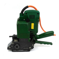
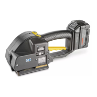
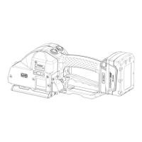
The FROMM A383.0001 is a pneumatic steel strapping tool designed for tensioning and sealing steel straps around packages. It is suitable for various industrial applications requiring secure packaging with steel strapping.

Function Description

The A383.0001 operates pneumatically to apply tension to steel strapping, create a seal, and cut the strap. The process involves feeding the strap around the package, loading it into the tool, tensioning the strap to the desired force, sealing the joint, and finally removing the tool. The tool is designed for ease of use, with controls for tensioning and sealing operations.

The tensioning cycle is initiated by pressing the motor valve lever, which causes the motor to tension the strap until it stalls or the lever is released. If the tensioning needs to be interrupted, a red lever can be pressed. The sealing action is performed by pressing the sealing valve lever, which activates the sealing mechanism and cuts the strap. The tool uses a sealless joint, forming an interlock by punching and deforming the strap ends together.

Important Technical Specifications

  • Dimensions (without suspension bracket):
    • Length: 420 mm / 16.5"
    • Width: 195 mm / 7.6"
    • Height: 350 mm / 13.7"
  • Weight: 23.1 kg / 50.82 lbs
  • Strap Width: 19 - 32 mm / 3/4" - 1 1/4" (refer to chart of types for specific models)
  • Strap Thickness: 0.63 mm - 1.3 mm / .025" - .050" (refer to chart of types for specific models)
  • Strap Quality: Fundamentally allows use of all current steel straps ranging from 700 to 1100 N/mm² (100,000 - 159,500 psi) in tensile. Straps with less than 600 N/mm² (87,000 psi) are not suitable.
    • Uniflex: Max. tensile strength of 850 N/mm² (123,000 psi)
    • Ultraflex: Max. tensile strength of 1100 N/mm² (160,000 psi)
  • Max. Tension: 10 kN (2240 lbs) or 15 kN (3360 lbs) depending on the model (e.g., A383/19/150/0.80-0.90, A383/25/150/0.80-0.90, A383/32/150/0.80-0.90 models support 15 kN).
  • Compressed Air:
    • Joining thread: G 1/4" min.
    • Max. air pressure: 6 bar / 87 psi
  • Air Consumption:
    • Tensioning: 22 NI / 0.80 cu.ft uncompressed air per second (with air motor running)
    • Sealing: 12.3 NI / 0.44 cu.ft uncompressed air per cycle
  • Sound Information: A-weighted equivalent continuous sound level at the workplace is typically 78 dB (A).
  • Vibration Information: Weighted effective value of acceleration is typically less than 2.5 m/s².

Usage Features

  • Operation Controls: The tool features a lever for general operation, a motor valve lever for tensioning, a sealing valve lever for sealing, and a flapper valve lever for strap loading and removal.
  • Strap Loading: Straps are loaded by lifting the flapper valve lever, inserting the two strap ends precisely upon another until they hit the strap stops, and then releasing the lever. The lower strap end should slightly protrude the base plate.
  • Tensioning: The motor valve lever is pressed down until the motor stalls, indicating sufficient tension. An interruption lever allows stopping the tensioning cycle if needed (e.g., for corner protection angles).
  • Sealing: The sealing valve lever is pressed and held until the strap is cut off, forming the sealless joint.
  • Tool Removal: After sealing, the cut strap end is held firmly, the flapper valve lever is lifted, and the tool is pushed away from the tensioned strap.
  • Suspension: The tool can be suspended on a balancer using various available suspension brackets (e.g., A38.2401 Normal, A38.2404 Vertical, A38.2407 Horizontal, A38.2410 Normal/Vertical/Horizontal with air supply).
  • Safety: Emphasizes wearing safety glasses with side shields (ANSI Standard Z87.1) and protective gloves when handling strap. Warns against positioning in-line with the strap during tensioning/sealing and using incorrect strap quality.

Maintenance Features

  • Compressed Air Connection: Requires clean compressed air, recommending an air unit with a water/dirt separator, pressure regulator with manometer, and lubricator. Maximum air tube length is 5 m / 15 ft.
  • Air-Unit Maintenance: Daily checks of air pressure and oil level. The water separator must be emptied before it's full, and the filter cleaned per manufacturer instructions.
  • Oil Level in Pressure Intensifier: Regular control is necessary. Too much or too little oil affects piston position and sealing quality.
    • Refilling Oil: Turn the tool with the flapper upward, remove the sealing screw, use wrench N7.3250 to move the sealing piston to the correct position, fill with SAE 10W-20 oil, and re-check piston position.
  • Cleaning: Regular cleaning of the feed wheel is necessary, especially with dirt/dust or painted straps, typically by blowing out with an air gun.
  • Lubrication: The gear is filled with MOLYKOTE BR 2 PLUS. All valve and movable parts should be greased with Mobilux EP2 or equivalent during exchange/repair.
  • Seal Control and Adjustment: Regular visual inspection of the seal is crucial.
    • Correct Seal: Upper strap hooks into lower one (1-1.5 mm min., 2 mm max.), upper strap clean-sheared, no scratch marks on lower strap.
    • Incorrect Seal (too high): Not deep enough, upper strap not sheared, insufficient tensile strength. Requires immediate readjustment.
    • Incorrect Seal (too low): Too deep, lower strap scratched, sufficient tensile strength but package strapping must be removed. Requires immediate readjustment.
    • Seal Adjustment: Depth of sealing mechanism and cutter can be adjusted by turning a screw with a screwdriver. Clockwise for excessive depth, counter-clockwise for insufficient depth (90° turn = 0.25 mm/.010" stroke correction).
    • Timing of Interlock: A holding air throttle (29) can be adjusted to influence interlock timing if straps don't interlock properly. Turning clockwise reduces holding air on the motor, allowing quicker interlock. Caution: Adjust to avoid tension marks on the bottom of the seal, which can cause premature punch wear.
  • Exchange of Wearing Parts:
    • Punch and Die Halves: Replaced if cutting edges are destroyed or heavily worn. Base plate must be removed. Mounting surfaces must be clean. Base plate screws tightened to 90 Nm. Screws N1.1323 and N1.1806 secured with Loctite 222.
    • Feed Wheel: Remove left strap stop, unscrew three screws, remove bearing cover, front distance ring, O-ring, and feed wheel. Assemble in opposite order, noting position.
    • Gripper: Remove left strap stop, bearing cover, front distance ring, O-ring, feed wheel, cross-recess screw, and holder. Clean groove and retighten holder after new gripper insertion. Screw N1.1807 secured with Loctite 222.
    • Cutter: Remove base plate, guard plate with guide, and right strap stop. Unscrew cutter screw M6 x 12 (using a hexagon socket spinner wrench). Replace cutter. Assemble in opposite order. Screw N1.1193 secured with Loctite 222.

Fromm A383.0001 Specifications

General IconGeneral
BrandFromm
ModelA383.0001
CategoryPackaging equipment
LanguageEnglish

Related product manuals