1.1.2 Switching loads via external relay without energy meter
The digital output signal of the Datamanager controls an external relay, which switches the load. The threshold
to switch ON/OFF can be set accordingly to the output power of the inverter.
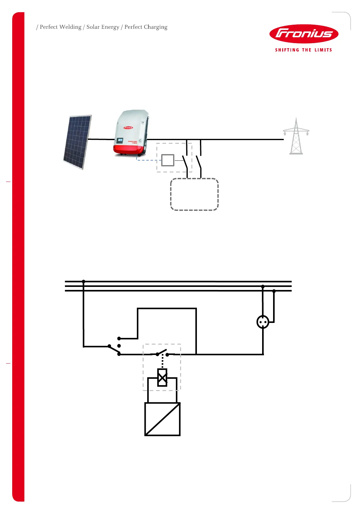
Figure 2 – Energy management function on external relay
1.2 Wiring detail
The following diagram shows a typical wiring example using an external relay and an override switch that allows
the additional, manual control of the load.
Figure 3 – Example connection diagram
This circuit consists of an override switch (1) where the load can be switched manually and the power outlet (2), which the
load can be connected to. With the external relay (3) the loads will be switched on/off controlled by the settings of the
Fronius Datamanager (4).
The output on the Datamanager is on I/O port 1 and the Minus pole (or GND on Datamanger 1.0). For further
details see next chapter.
Fronius inverter with
Datamanager
Fronius inverter with
Datamanager

 Loading...