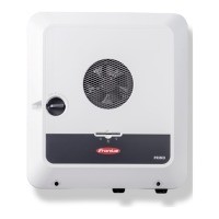
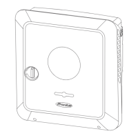
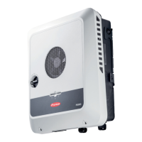
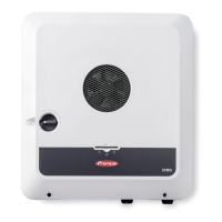
Do you have a question about the Fronius Primo GEN24 4.0 and is the answer not in the manual?
Details the meaning of warning, caution, and note symbols used.
Specifies qualifications and responsibilities for personnel involved in maintenance and servicing.
Covers EMC compliance and the system's backup power functions.
Outlines user responsibility for data and manufacturer's rights over documentation.
Details the requirements for connecting the protective earth conductor.
Explains the inverter's role in converting DC to AC and its operational capabilities.
Details how the inverter can be expanded with optional functions via Fronius UP.
Defines the inverter's intended purpose and actions considered improper use.
Describes the inverter's cooling system and precautions for heat dissipation.
Explains how the inverter can be found and communicated with locally.
Illustrates symbols used to denote different system components and modes.
Diagrams showing system configurations with inverter and battery.
Illustrates the four different energy flow directions in hybrid inverter systems.
Describes various operating states for battery systems.
Explains the purpose and conditions for entering energy saving mode.
Details the criteria for the battery and inverter to enter and exit energy saving mode.
Describes how energy saving mode is indicated on the inverter and in Solar.web.
Fronius's disclaimer on third-party batteries and operational limitations.
Compatibility tables for BYD Battery-Box Premium and LG FLEX batteries.
Instructions for manually starting the system and backup power operation.
Details integrated AC relays for coupling and system protection units.
Explains wired shutdown functionality and residual current monitoring.
Describes insulation monitoring and Arc Fault Circuit Interrupter functionality.
Information on inverter safe states and integrated surge protection.
Diagram and labels for the inverter's connection area terminals.
Details on the DC disconnector and the data communication interfaces.
Explains the function of buttons, LEDs, and status indicators.
Details on the PV Point for backup power supply with limitations.
Explains the PV Point Comfort's continuous supply and automatic switching.
Lists essential requirements for enabling the Full Backup power mode.
Describes automatic switching to backup power for various country standards.
Covers quick-lock system, warning notices, and system component compatibility.
Criteria and permissible substrates for selecting an installation location.
Instructions for selecting fixing materials and installing the mounting bracket.
Details on permissible cables for electrical connections and data communication.
Safety warnings and procedures for connecting the inverter to the public grid.
Guidelines for connecting PV modules, including safety and array configuration.
Safety warnings and procedures for connecting the battery on the DC side.
Installation and testing procedures for PV Point (OP) backup power.
Instructions for user login and selecting the interface language.
Configuration steps for PV generator, battery, and primary meter settings.
Settings for backup power modes, DRM, and inverter parameters.
Configuration of self-consumption optimization and battery management.
Steps for establishing network connections via LAN or WLAN.
Configuration of Modbus RTU interfaces, baud rate, and parity.
Enabling remote control and activating the Fronius Solar API.
Guidelines for country setup, requesting codes, and feed-in limitations.
Setting control priorities and connection diagrams for relays.
Configuration of DNO rules for power management with 4 relays.
Configuration of DNO rules for power management with 3 relays.
Configuration of DNO rules for power management with 2 relays.
Explains SPD protection, triggers, and safety precautions.
Details on the scope of supply and installation of the DC Connector Kit.
Safety warnings and configuration steps for the PV Point Comfort.
Guidelines for inverter maintenance and cleaning procedures.
Warnings regarding electrical voltage and residual voltage from capacitors.
Notes on potential issues and precautions for dusty operating environments.
Information on responsible disposal of electrical equipment and packaging.
Details on obtaining warranty terms and registering the system.
Lists components required for automatic full backup power changeover.
Details components for manual full backup power changeover.
Explains how status codes are displayed and provides remedies for common issues.
Detailed DC and AC input/output data for various GEN24 models.
Specifications for protection devices and data communication interfaces.
Circuit diagram for connecting GEN24 with BYD Battery-Box Premium HV.
Circuit diagram for connecting GEN24 with multiple BYD Battery-Box Premium HV units.
Circuit diagram for connecting GEN24 with LG FLEX batteries.
Various circuit diagrams for backup power configurations (PV Point, PV Point Australia, etc.).
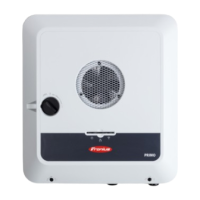
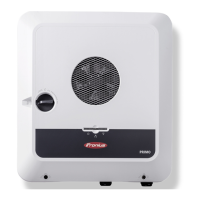
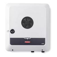
Detailed dimensional drawings of the Fronius Primo GEN24 3-6 kW inverter.
| Model | Fronius Primo GEN24 4.0 |
|---|---|
| Type | Hybrid Inverter |
| Rated Power | 4.0 kW |
| Dimensions | 530 x 474 x 165 mm |
| IP Rating | IP66 |
| Grid frequency | 50 / 60 Hz |
| THD | < 3% |
| Number of MPP trackers | 2 |
| Max. input current per MPP tracker | 12 A |
| Maximum Input Voltage | 600 V |
| Operating Temperature Range | -25°C to +60°C |
| Communication Interfaces | Ethernet |
| Max. apparent AC power | 4.6 kVA |
| Max. DC power | 6 kW |
| Cooling | Active cooling |
| Warranty | 5 years |

