EasyManua.ls Logo

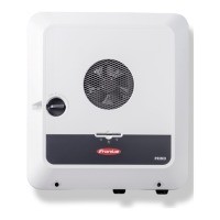
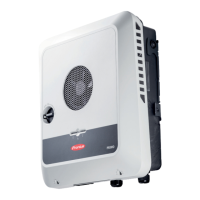
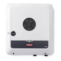
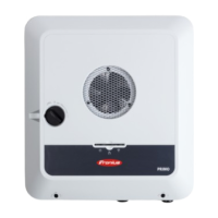
Fronius Primo GEN24 10.0 Plus User Manual

Fronius Primo GEN24 10.0 Plus
208 pages
To Next Page IconTo Next Page
Page #1 background imageLoading...
Page #1 background image
Op erating
Instructions
Fronius Primo GEN24
8.0 Plus / 10.0 Plus
42,0426,0419,EN 019-06112023
EN
Operating Instructions

Table of Contents

Question and Answer IconNeed help?

Do you have a question about the Fronius Primo GEN24 10.0 Plus and is the answer not in the manual?

Fronius Primo GEN24 10.0 Plus Specifications

General IconGeneral
AC Nominal Output10.0 kW
Protection ClassIP66
Operating Temperature Range-25°C to +60°C
TopologyTransformerless
Max. Output Current16 A
AC Nominal Voltage400 V
THD< 3%
AC Grid Frequency50 / 60 Hz
Number of MPP Trackers2
CoolingActive cooling
Max. Apparent AC Power10.0 kVA
Max. DC Power15, 000 W
Max. DC Input Power15, 000 W
Warranty5 years (extendable)

Summary

Fronius Primo GEN24

Suitable batteries

Manual system start

Protection of people and equipment

Central grid and system protection

Explains the use of integrated AC relays for coupling switches with protection units.

AFCI - Arc Fault Circuit Interrupter (Arc Guard)

Describes the AFCI's role in protecting against arcing faults and contact faults.

Control elements and connections

Backup power variant - PV Point (OP)

PV Point (OP)

Explains the functionality of the PV Point terminal for supplying power during grid failures.

Backup power variant - Full Backup

Prerequisites for backup power mode

Lists essential requirements for enabling the inverter's backup power function, including compatible batteries and cabling.

Transitioning from feeding energy into the grid to backup power mode

Describes the process and steps involved when the system switches from grid-connected operation to backup power mode.

Transitioning from backup power mode to feeding energy into the grid

Explains the process of returning to grid operation from backup power mode.

Installation

Installation location and position

Choosing the location of the inverter

Provides criteria for selecting an appropriate installation location for the inverter, considering temperature, humidity, and clearances.

Install the mounting bracket and hang up the inverter

Prerequisites for connecting the inverter

Permissible cables for the electrical connection

Specifies permissible cable cross-sections and types for grid, backup power, PV/BAT, and ground connections.

Connecting the inverter to the public grid (AC side)

Connecting the inverter to the public grid (AC side)

Explains the necessity of connecting the neutral conductor and ensuring proper grounding of the AC cable.

Connecting solar module strings to the inverter

Connecting the solar module strings to the inverter

Provides step-by-step instructions for connecting solar module strings to the inverter's DC inputs.

Connecting the battery to the inverter

Safety

Lists critical safety warnings related to incorrect operation, voltage exposure, and terminal conditions.

Connecting the battery on the DC side

Cautions about operating the battery above permissible altitudes and emphasizes following manufacturer instructions.

Connecting backup power - PV Point (OP)

Installation

Advises that loads connected to the OP terminal must be protected by a residual-current circuit breaker and requires a neutral-earth connection.

Connecting backup power - Full Backup

Automatic switch to backup power 1-pin separation, e.g. Austria or Australia

Explains the cabling requirements for backup power circuits and the 1-pin disconnection from the grid.

Closing and commissioning the inverter

Starting the inverter for the first time

Outlines the initial setup process, including country selection and configuration wizard.

Installation with the app

Installation using the web browser

Settings - user interface of the inverter

Device configuration

Functions and I/Os

Energy management

Self-Consumption Optimization

Explains how to set operating modes for self-consumption optimization and target feed-in values.

Battery Management

Covers time-dependent battery control, charging permissions, and power limitations.

System

Communication

Safety and grid requirements

Country setup

Warns about unauthorized access and incorrect parameter settings, emphasizing installer-only adjustments.

Feed-in limitation

Explains how energy companies may stipulate feed-in limitations and how they are accounted for.

Dynamic power regulation with several inverters

I/O power management

Options

Surge protective device (SPD)

Installation

Commissioning the inverter

DC Connector Kit GEN24

Installation

Details the installation process for the DC Connector Kit, including cable dimensioning and warnings.

Commissioning the inverter

Care, maintenance and disposal

Safety

Highlights critical safety warnings regarding grid voltage, DC voltage, and residual voltage from capacitors.

Components for switching to backup power

Components for automatic Full Backup backup power changeover

Lists components required for automatic Full Backup changeover, including Smart Meters and protection units.

Status codes and remedy

Technical data

Circuit diagrams

Fronius Primo GEN24 and BYD Battery-Box Premium HV

Fronius Primo GEN24 with two BYD Battery-Box Premium HV connected in parallel

Fronius Primo GEN24 and LG RESU FLEX

Circuit Diagram - PV Point (OP)

Automatic switch to backup power 1-pin single separation - e.g. Austria

Automatic switch to backup power 2-pin single separation - e.g. Germany

Automatic switch to backup power 2-pin double separation with ext. grid and system protection - e.g. Italy

Dimensions of the inverter

Related product manuals