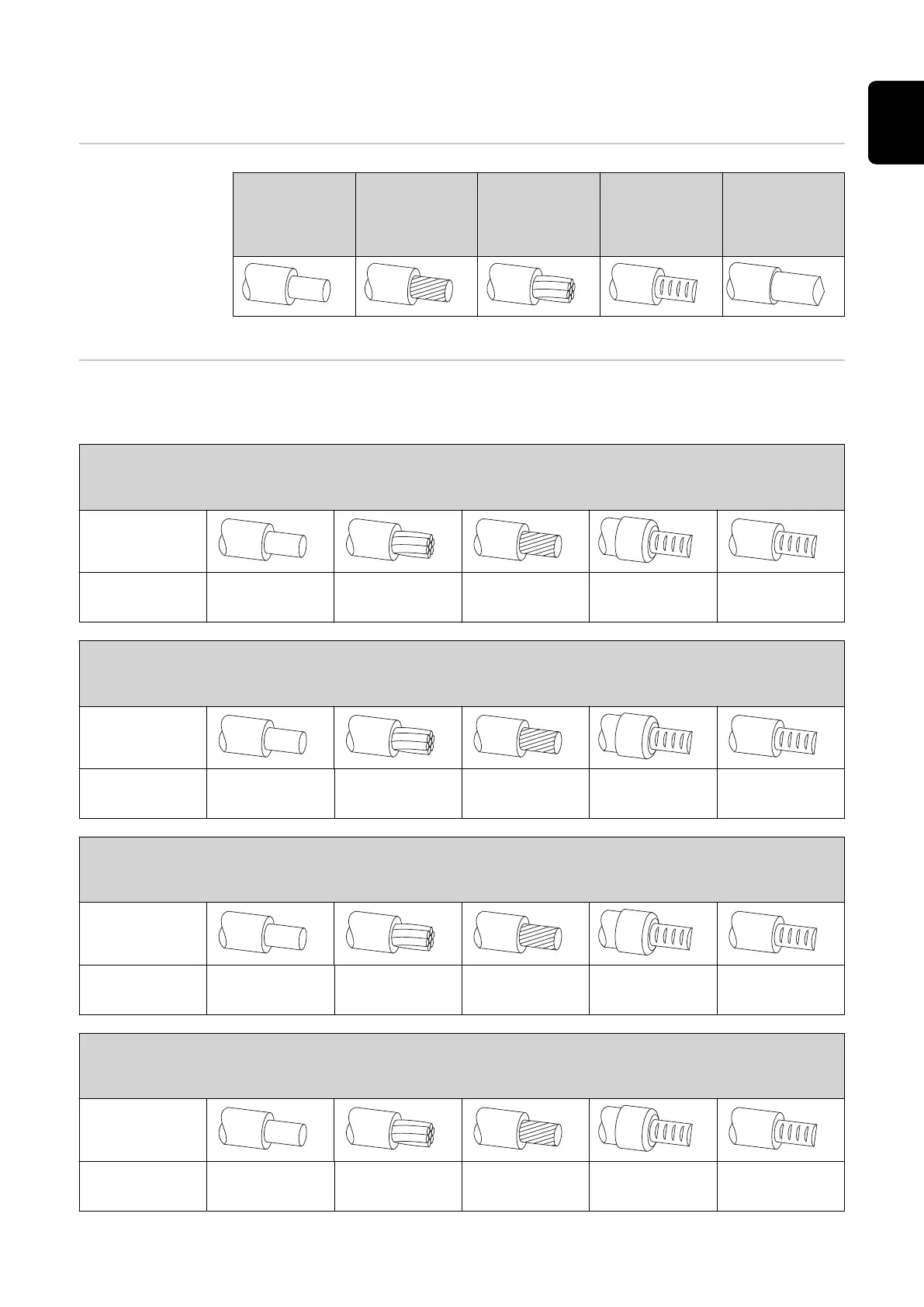
Prerequisites for connecting the inverter
Different cable
types
Solid
Fine-stran-
ded
Multi-stran-
ded
Fine-stran-
ded with fer-
rule and col-
lar
Fine-stran-
ded with fer-
rule without
collar
Permissible
cables for the
electrical con-
nection
Round copper conductors can be connected to the terminals of the inverter as
described below.
Grid connections with push-in terminal*
Select a sufficiently large cable cross section based on the actual device output.
Number of
pins
3
2.5-16 mm
2
AWG 14-6
2.5-16 mm
2
AWG 14-6
2.5-16 mm
2
AWG 14-6
2.5-16 mm
2
AWG 14-6
2.5-16 mm
2
AWG 14-6
Grid connections backup power with push-in terminal*
Select a sufficiently large cable cross section based on the actual device output.
Number of
pins
3
1.5-10 mm
2
AWG 16-8
1.5-10 mm
2
AWG 16-8
1.5-10 mm
2
AWG 16-8
1.5-6 mm
2
AWG 16-10
1.5-6 mm
2
AWG 16-10
PV/BAT connections with push-in terminal**
Select a sufficiently large cable cross section based on the actual device output.
Number of
pins
2 x 5
4-10 mm
2
AWG 12-8
4-10 mm
2
AWG 12-8
4-10 mm
2
AWG 12-8
4-6 mm
2
AWG 12-10
4-6 mm
2
AWG 12-10
Ground electrode terminal (6-pin)
Select a sufficiently large cable cross section based on the actual device output.
Number of
pins
2
2.5-16 mm
2
AWG 14-6
2.5-16 mm
2
AWG 14-6
2.5-16 mm
2
AWG 14-6
2.5-16 mm
2
AWG 14-6
2.5-16 mm
2
AWG 14-6
67
EN

 Loading...


