Do you have a question about the Fronius Primo GEN24 3.6 and is the answer not in the manual?
Details the meaning of warning, caution, and note symbols used in the manual.
Covers safe operation, qualified personnel, and adherence to local regulations.
Specifies environmental operating limits and qualifications for service personnel.
Details noise levels and electromagnetic compatibility considerations for the device.
Explains backup power features and factors influencing its operation.
Covers data safety, manual copyright, and essential protective earthing requirements.
Explains the inverter's basic function, power conversion, and operational modes.
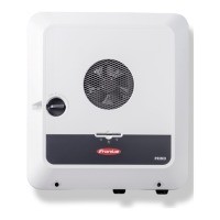
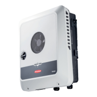
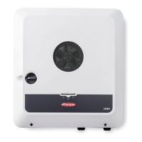
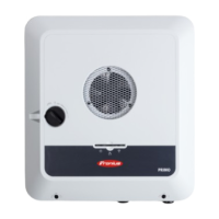
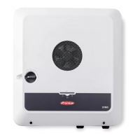
Lists included components and defines the inverter's proper application.
Details the inverter's cooling system and its connection to the Solar.web monitoring platform.
Describes how to communicate locally with the inverter using mDNS.
Visual guide to understanding various system configurations and component symbols.
Illustrates system configurations with battery, including single and multiple Smart Meters.
Details operation with battery, Ohmpilot, and additional inverters, including backup functions.
Explains the four energy flow directions and battery system operating states.
Covers conditions for entering and exiting energy saving mode, and its indication.
Lists compatible third-party batteries and explains limitations for operation.
Details requirements and steps for manual system start after shutdown.
Explains system protection features like RCMU, safe states, and surge protection.
Identifies connection terminals and components on the inverter's interface.
Details the DC disconnector settings and the components in the data communication area.
Explains the meaning of button functions and LED indicators for system status.
Provides a detailed diagram of the inverter's input/output connections.
Explains the PV Point backup power feature and its operational parameters.
Lists requirements for using the Full Backup function and transition procedures.
Details cabling requirements for backup power circuits based on regional standards.
Covers quick-lock system, warning notices, and compatibility checks.
Specifies criteria for choosing a suitable location for the inverter.
Provides instructions for selecting materials and installing the mounting bracket.
Details permissible cables for electrical connections and data communication.
Step-by-step guide for connecting the inverter to the AC grid.
Instructions for connecting PV modules, including safety and array configuration.
Guide for connecting the battery to the inverter's DC inputs.
Details the installation process for the optional DC Connector Kit GEN24.
Provides guidance on maintaining the inverter and safe cleaning practices.
Covers maintenance procedures and safety warnings related to electrical hazards.
Addresses challenges in dusty conditions and proper end-of-life disposal.
Provides detailed DC input electrical specifications for various inverter models.
Lists AC electrical data, efficiencies, dimensions, and environmental ratings.
Details protection mechanisms, safety classes, and communication protocols.
Illustrates the wiring for the PV Point backup power output.
Shows wiring for 1-pin separation backup power switching, e.g., Austria.
Details wiring for 2-pin separation backup power switching, e.g., Germany.
Wiring diagram for connecting GEN24 with BYD Battery-Box Premium HV.
Provides the physical dimensions and mounting details of the inverter unit.
| Model | Primo GEN24 3.6 |
|---|---|
| Category | Inverter |
| AC nominal output | 3.6 kW |
| Dimensions | 530 x 474 x 165 mm |
| Protection class | IP66 |
| Operating temperature range | -25°C to +60°C |
| Max. output current (at grid voltage) | 16 A |
| AC nominal voltage | 230 V |
| Grid frequency | 50 / 60 Hz |
| THD | < 3% |
| Number of DC connections | 2 |
| Max. charging / discharging current | 50 A |
| Number of MPP Trackers | 2 |
| Max. apparent AC power | 3.6 kVA |
| Power factor (cos φac,r) | 1 |
| DC input voltage | 1000 V |
| Battery voltage range | 40-59 V |
| Warranty | 5 years |
