Do you have a question about the Fronius Primo GEN24 208-240 and is the answer not in the manual?
Explains safety symbols, risks of misuse, and personnel qualifications.
Guidelines for operating and storing the device outside stipulated areas.
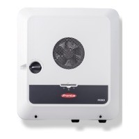
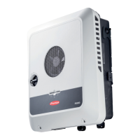
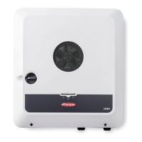
Introduces the device concept, intended use, and scope of supply.
Explains the inverter's purpose, restrictions, and thermal concept for operation.
Covers user responsibility for data backup and monitoring via Fronius Solar.web.
Details local communication via mDNS and explains different operating modes.
Explains RSD triggers, backup mode limitations, and system labeling.
Describes the PLC transmitter's role in rapid shutdown per NEC standards.
Details Wired Shutdown, RCMU, Insulation Monitoring, and Arc Fault Circuit Interrupter functions.
Illustrates and labels all connection terminals and ports on the inverter.
Explains the connection area divider, ground electrode terminal, and conduit connections.
Details the DC disconnector, data communication area switches, and LEDs.
Describes optical sensor, communication LED, LAN, I/O, WSD, and Modbus terminals.
Explains the meaning of sensor functions and various inverter status LED indications.
Explains PV Point terminal for backup power, its limits, voltage, current, and operation.
Covers quick-fastener system, device warning notices, and general installation preparation.
Guides on choosing location, environmental criteria, and permissible installation substrates.
Details suitability for outdoor use, sunlight avoidance, altitude limits, and environmental restrictions.
Illustrates and describes correct and incorrect installation orientations.
Provides instructions and warnings for drilling out knockouts using a step drill bit.
Covers material selection, bracket properties, avoiding deformation, and fitting to walls.
Details using a specific kit for mounting on masts or beams.
Instructions for affixing bracket to rails and clipping the inverter onto the bracket.
Specifies cable types, sizes, and push-in terminal requirements for various connections.
Details cable diameter for terminals and permitted cables for data communication.
Provides specifications for WSD and Modbus connections, including distance and stripping length.
Details IO connection specifications, LAN recommendations, and AC fuse protection requirements.
Crucial safety warnings regarding incorrect operation, grid voltage, and terminal handling.
Illustrates various grid types (Split Phase, WYE) compatible with the inverter.
Important notes on neutral conductor connection, ungrounded grids, and ground conductor routing.
Covers PV module voltage, temperature coefficients, and safety for DC connections.
Details PV generator setup, including module array settings and current limits.
Step-by-step instructions for connecting PV module strings to the inverter.
Safety warnings for PV Point installation, limitations, and power supply considerations.
Step-by-step guide for installing the PV Point connection, including knockout preparation.
Explains how to connect Modbus participants and sets limits for primary/secondary meters.
Instructions for routing communication cables and using terminating resistors for reliability.
Details WSD installation, bypass removal, master/slave configuration, and distance limits.
Instructions for closing the inverter cover and setting the DC disconnector to 'On'.
Guides for installing the inverter using the Solar.start app or a web browser.
Step-by-step guide for installation using a network cable (LAN).
Instructions for safely turning the inverter off and on using the circuit breaker and DC disconnector.
Explains how to log in, user authorization, and changing the inverter's display language.
Details configuring PV generator, meter, backup power, load management, and inverter standby.
Explains PV generator parameters like Mode, Peak Manager, and ripple control signal settings.
Covers false alarm reduction, insulation monitoring, and backup power voltage/surge protection settings.
Explains restart delays, attempts, frequency monitoring, and short circuit switch-off for backup power.
Describes defining load management rules, load control modes, thresholds, and runtimes.
Covers system name, time sync, firmware updates, and setup wizard.
Explains restoring defaults, accessing logs, and managing inverter licenses.
Details activating support users, creating support info, and enabling remote maintenance.
Guides on network server addresses, LAN, and WLAN connection setup.
Explains Modbus RTU/TCP interface settings, including baud rate, parity, and meter addresses.
Covers remote control by grid operators and cloud integration for virtual power plants.
Describes Solar API access and checking internet service connection status.
Details country setup, authorized access, parameter adjustments, and requesting inverter codes.
Explains how grid operators set feed-in limits and different limit types.
Covers DNO settings, input patterns, power factor, DNO feedback, and control priorities.
Instructions for using pre-configured files for 4-relay operation via mobile device.
Interface view of configuring I/O power management rules with active power and power factor settings.
Instructions for using pre-configured files for 3-relay operation via mobile device.
Interface view of configuring I/O power management rules with active power and power factor settings.
Instructions for using pre-configured files for 2-relay operation via mobile device.
Interface view of configuring I/O power management rules with active power and power factor settings.
Instructions for using pre-configured files for 1-relay operation via mobile device.
Interface view of configuring I/O power management rules with active power and power factor settings.
General operational notes, copyright, and instructions for cleaning the inverter.
Guidance on cleaning the inverter's heat sink and fan in dusty conditions to prevent power loss.
Instructions for proper disposal of the device and packaging materials according to regulations.
Information on finding warranty conditions online and registering the product.
Explains where status codes are displayed (UI, Event Log, Notifications, Solar.web).
Details remedies for common status codes like WSD Open and ArcContinuousFault.
Lists DC input specifications including voltage, current, and power ratings.
Lists AC output specifications including power, voltage, current, and protection.
Covers AC output fault current, frequency, THD, power factor, and general inverter data.
Details protection devices (AFCI, Rapid shutdown, RCMU) and PV Point output specifications.
Covers WLAN, Ethernet, WSD, Modbus, and digital input specifications.
Specifies digital output power and data for Full Backup operation.
Lists DC input specifications for the 10.0 kW model.
Covers AC output and general specifications for the 10.0 kW model.
Details protection devices and PV Point output for the 10.0 kW model.
Covers data communication and Full Backup specifications for the 10.0 kW model.
Details WLAN specifications and provides explanations for footnotes related to technical data.
Provides general data for the integrated DC disconnector.
Lists rated operating current and breaking capacity for the DC disconnector.
Provides the circuit diagram for the PV Point emergency power terminal.
Shows detailed dimensional drawings of the inverter with measurements.
| Type | Hybrid Inverter |
|---|---|
| AC voltage range | 183 - 264 V |
| AC grid frequency | 60 Hz |
| THD | < 3% |
| Max. input voltage | 600 V |
| Number of DC connections | 2 |
| Number of MPP trackers | 2 |
| Max. battery charging / discharging current | 22 A |
| Protection class | IP66 |
| Model | Primo GEN24 208-240 |
| Battery Compatibility | BYD Battery-Box Premium HVS/HVM |
| Communication Interfaces | Ethernet, RS485 |
| Operating Temperature Range | -25°C to +60°C |
| Cooling | Active cooling |
| Warranty | 5 years (extendable) |

