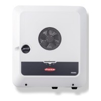
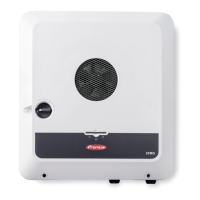
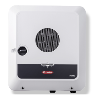
LED status indicator
The inverter is operating correctly, a network fault is in-
dicated.
Lights up red
The network connection is active.
Lights up blue
The inverter is performing an update.
/ Flashing blue
There is a service message.
Lights up white
Schematic in-
ternal wiring of
IOs
The V+/GND pin provides the possibility of feeding in a voltage in the range of
12.5 to 24 V (+ max. 20%) using an external power supply unit. Outputs IO 0 - 5
can then be operated using the external voltage that has been fed in. A maximum
of 1 A may be drawn per output, whereby a total of max. 3 A is permitted. The
fuse protection must take place externally.
CAUTION!
Danger from polarity reversal at the terminals due to improper connection of
external power supply units.
This may result in severe damage to the inverter.
▶
Check the polarity of the external power supply unit with a suitable measur-
ing device before connecting it.
▶
Connect the cables to the V+/GND outputs while ensuring the correct polar-
ity.
IMPORTANT!
If the total output (6W) is exceeded, the inverter switches off the entire external
power supply.
12 V DC
500 mA
V+ V+
GND
IO0
IO1
IN8
IN9
IN10
IN11
IN6
IN7
IO4
IO5
IO2
IO3
GND
(1)
12 V
USB
TYP A
5 V
IO4
V+
V+
IO0
IO2
IN6
IN8
IN10IN11
IN9
IN7
IO5
IO3
IO1
GND
GND
M0-
M0+
M1-
M1+
SHIELD
SHIELD
V+ V+
GND GND
V+
V+
M0+
SHIELD
M1+
GND
M1-
SHIELD
M0-
GND
(1) Current limitation
28

 Loading...

