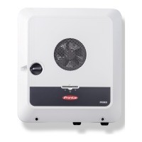
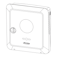
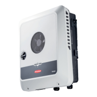
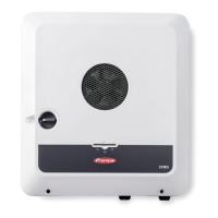
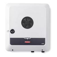
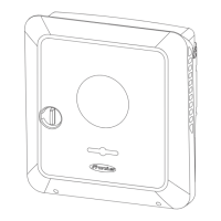
DC disconnector The DC disconnector has three switch
settings:
(1) Locked/off (turned to the left)
(2) Off
(3) On
IMPORTANT!
In switch settings (1) and (3), the in-
verter can be secured to prevent it
from being switched on/off using a
standard padlock. The national
guidelines must be complied with in
this respect.
Data communic-
ation area
*Please note that the BAT (RJ45) interface is reserved for future use and is not currently available.
Operating LED
Indicates the inverter operating
status.
WSD (wired shutdown) switch Defines the inverter as the WSD mas-
ter or WSD slave.
Position 1: WSD master
Position 0: WSD slave
Modbus 0 (MB0) switch Switches the terminating resistor for
Modbus 0 (MB0) on/off.
Position 1: Terminating resistor on
(factory setting)
Position 0: Terminating resistor off
Modbus 1 (MB1) switch Switches the terminating resistor for
Modbus 1 (MB1) on/off.
Position 1: Terminating resistor on
(factory setting)
Position 0: Terminating resistor off
25
 Loading...

