11
EN
If AC cables are laid over the shaft of the DC main switch or across the connection block
of the DC main switch, they may be damaged when the inverter is swung in, or they may
even prevent the inverter from being swung in.
IMPORTANT! Do not lay AC cables over the shaft of the DC main switch or across the con-
nection block of the DC main switch!
E.g.: AC cable
If overlength AC or DC cables are to be laid
in loops in the connection area, attach the
cables with cable ties to the eyelets provi-
ded on the top and bottom of the connecti-
on block.
Maximum fuse
rating on alternat-
ing current side
PE
PE
PE
P
E
P
E
P
E
max. C 25 A
AC ~
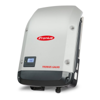
Inverter Phases Max. output Max. fuse rating
Fronius Galvo 1.5 1 1500 W 1 x C 25 A
Fronius Galvo 2.0 1 2000 W 1 x C 25 A
Fronius Galvo 2.5 1 2500 W 1 x C 25 A
Fronius Galvo 3.0 1 3000 W 1 x C 25 A
Fronius Galvo 3.1 1 3100 W 1 x C 25 A
 Loading...


