14
Connecting alu-
minum cables
The DC-side terminals are designed for connecting single-wire, round aluminum cables.
The following points must be taken into account when connecting aluminum cables due to
the non-conducting oxide layer of aluminum:
- Reduced rated currents for aluminum cables
- The connection requirements listed below
Connection Requirements:
Carefully clean off the oxide layer of the stripped end of the cable, e.g., using a knife.
IMPORTANT Do not use brushes, files or sandpaper. Aluminum particles may get stuck
and can transfer to other cables.
After removing the oxide layer of the cable end, rub in a neutral grease, e.g., acid- and
alkali-free Vaseline.
Then immediately connect it to the terminal.
Repeat the steps above whenever the cable is disconnected and then reconnected.
Notes regarding
dummy devices
A dummy device is not suitable for connecting operationally to a photovoltaic system, and
must only ever be used for demonstration purposes. Dummy devices are indicated as such
on their rating plate.
IMPORTANT! Never connect DC cables to the DC connection sockets on a dummy de-
vice.
The connection of de-energised cables or sections of cable for demonstration purposes is
permissible.
Inverter DC con-
nection
IMPORTANT! Check the polarity and voltage of the solar module strings: the permitted
voltage is:
- Max. 420 V
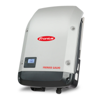
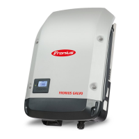
for Fronius Galvo 1.5-1
for Fronius Galvo 2.0-1
- Max. 550 V
for Fronius Galvo 2.5-1
for Fronius Galvo 3.0-1
for Fronius Galvo 3.1-1
The difference between the individual solar module strings must not exceed 10 V.
NOTE! Take into account local specifications when configuring cable cross sec-
tions.
1
2
3
NOTE! Only break out as many target break points as the number of cables that
are provided (e.g. if there are two DC cables, then break out two recesses).
 Loading...


