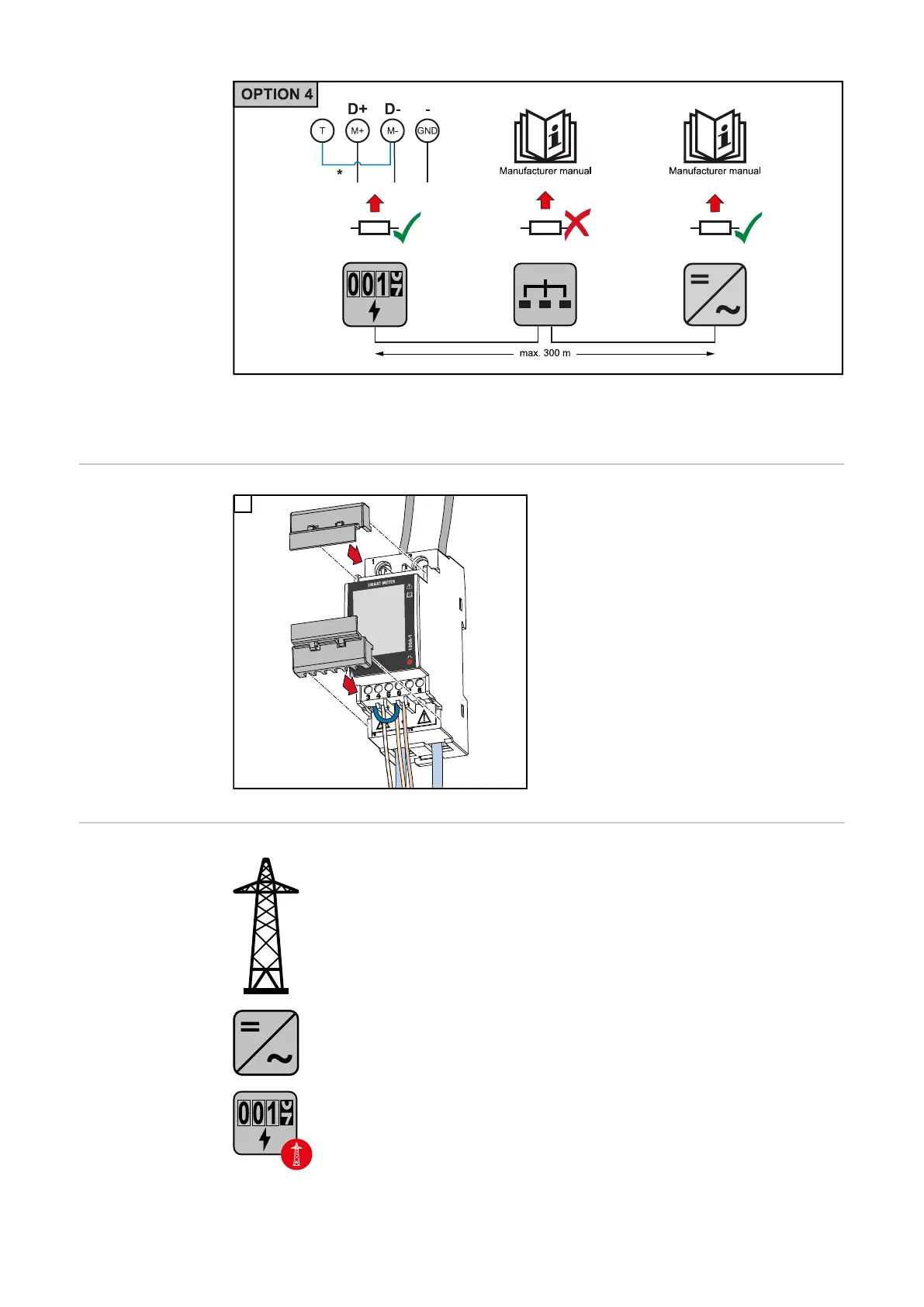
* The terminating resistor is integrated in the Fronius Smart Meter TS and is manufac-
tured with a bridge between the M and T connections (T = termination).
Mounting the
connection cover
1
Insert the connection covers into the
guides and press firmly.
IMPORTANT!
When fitting the connection covers, ensure
that the cables are not kinked, pinched,
crushed or otherwise damaged.
Multi-meter sys-
tem - Explanation
of symbols
Grid
supplies the loads in the system if insufficient power is being generated
by the solar modules or supplied by the battery.
Inverter in the system
e. g. Fronius Primo, Fronius Symo, etc.
Utility meter
Measures the measurement data relevant for billing amounts of energy
(in particular kilowatt hours of energy sourced from the grid and energy
fed into the grid). Based on the relevant billing data, the electricity
retailer will invoice the energy sourced from the grid and the purchaser
of the surplus energy will reimburse the energy fed into the grid.
24

 Loading...


