105
EN-US
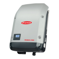
- fit SymoPS using thirteen 4x9 TX20
screws (5)
[2 Nm]
Thread in and connect all cables and
plug connections (1-4)
NOTE!
Ensure that the ferrite cores and their
holders (3) are fitted correctly
Close the inverter and place it in the
wall bracket (see "Opening and Clo-
sing the Device")
After switching on the inverter, carry out a
fan test via the display (see Operating Inst-
ructions)
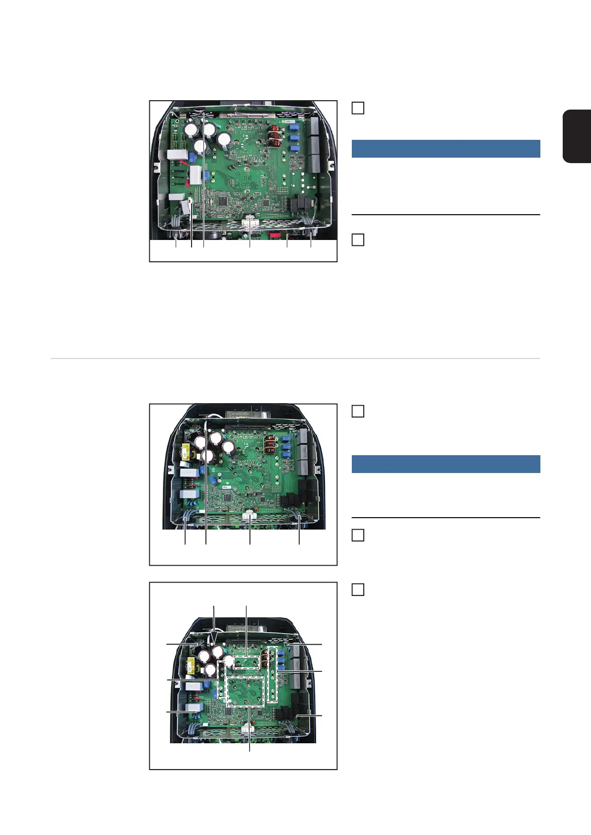
Replacing the
Power PC board -
DuoPS
Removing DuoPS:
Take the inverter out of the wall bra-
cket and open it (see "Opening and
Closing the Device")
NOTE!
When undoing the AC plug connection
(1), hold the PC board at the top right
edge of the DuoFIL
Disconnect all cables and plug connec-
tions (1)-(4) and thread them out
Undo the fifteen 4x9 TX20 screws (5)
(1)(3) (2) (4) (4) (3)
5
6
(1) (3)(2) (4)
1
2
(5)
(5)
(5)
(5)
(5)
(5)
(5)
(6)
(6)
3
 Loading...