90
Commissioning the CMT4000 Advanced
Fitting the system
components
(overview)
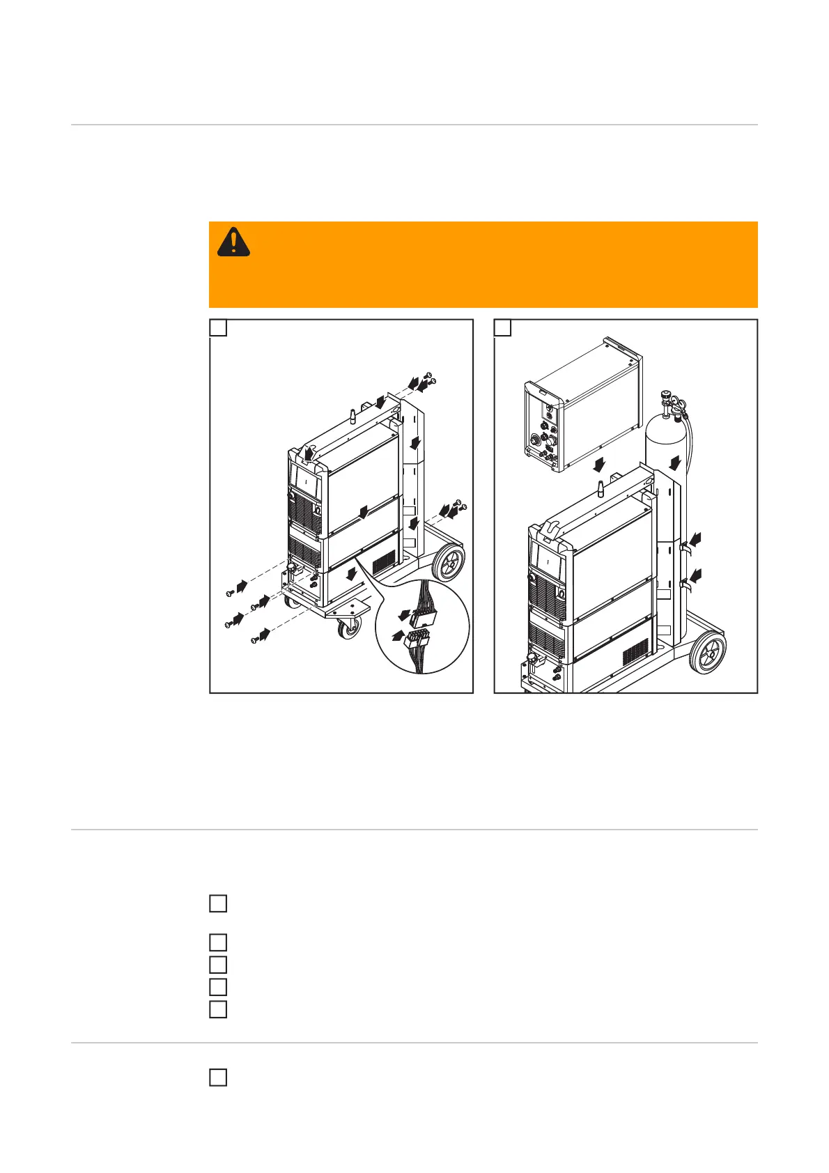
The diagram below is intended to show you how to fit the individual system components.
For detailed information about the individual steps, please refer to the operating instruc-
tions for the system components.
Fitting the system components Installing the wire-feed unit and setting up the gas cy-
linder
1)
Fasten the cooling unit and power source to the back of the machine as well using 2
screws in each case
2)
Cylinder holder extension
Connecting the
interconnecting
hosepack, CMT
welding torch and
wire buffer
For detailed information about the individual steps, please refer to the relevant operating
instructions for the system components.
Fasten the strain-relief devices of the CMT interconnecting hosepack to the trolley and
the wire-feed unit
Connect the CMT interconnecting hosepack to the power source and wire-feed unit
Connect the CMT hosepack to the CMT drive unit
Connect the wire buffer
Connect the CMT welding torch to the wire-feed unit
Other tasks Connect the wirefeeding hose
WARNING! If gas cylinders topple over, there is a risk of very serious injury and
damage. Place gas cylinders on a solid, level surface so that they remain stable.
Secure gas cylinders to prevent them from falling over.
Observe the safety rules of the gas cylinder manufacturer.
11
1
4
7
8
9
6
5
2
2
3
3
11
1)
2)
10
10
5
1
2
1
2
3
4
5
1
 Loading...