Home
Fuji Electric
Measuring Instruments
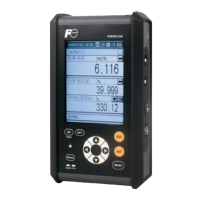
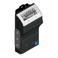
FSC-2
Page 196
Fuji Electric FSC-2 - Page 196
196 pages
Manual
To Previous Page
To Previous Page
Loading...
Global Sales Section
Instrumentation & Sensors Planning Dept.
1, Fuji-machi, Hino-city
, T
okyo 191-8502, Japan
http://www
.fujielectric.com
Phone: +81-42-514-8930 Fax: +81-42-583-8275
http://www
.fujielectric.com/products/instruments/
195
Table of Contents
Main Page
PREFACE
2
CONTENTS
3
WARNING SYMBOLs AND THEIR MEANINGs
6
SAFETY PRECAUTIONS
7
1. OVERVIEW
10
2. CHECK OF DELIVERED ITEMS
11
2.1 On purchase of flow transmitter (type: FSC)
11
2.2 On purchase of transit time detector (type: FSS)
12
2.3 On purchase of flow velocity distribution measurementdetector (type: FSD)
13
3. CHECK MODEL AND SPECIFICATION
14
4. NAME AND EXPLANATION OF EACH PART
17
4.1 Name and explanation of main unit and detector
17
4.2 Explanation of keys
19
4.3 Handling of SD memory card
20
4.3.1 Precautions for handling of SD memory card
20
4.3.2 Formatting forms
20
4.3.3 Insertion and removal
21
4.3.4 Data recording to SD memory card
22
5. CHARGE METHOD AND OPERATION POWER SUPPLY
25
5.1 Operating power supply
25
5.2 Turning on the power and language preference
27
5.3 Power OFF
28
6. WIRING
29
6.1 Diagram
29
6.2 Connection of dedicated cables
29
6.3 Connection of analog input/output cable(4 to 20 mA DC)
30
6.4 Connection of USB cable
30
7. INPUT OF PIPING SPECIFICATIONS
31
7.1 Display of pipe setup screen
31
7.2 Entry of site name (not required measurement)
34
7.3 Outer diameter of piping (unit: mm)
37
7.4 Piping material
38
7.5 Wall thickness (unit: mm) (range: 0.1 to 100.00mm)
39
7.6 Lining material
40
7.7 Lining thickness (unit: mm) (range: 0.01 to 100.00 mm)
41
7.8 Kind of fluid
42
7.9 Viscosity
43
7.10 Selection of sensor mounting method
44
7.11 Kind of sensor
45
7.12 Transmission voltage (used when an indicator is 1 orless during measurement)
46
7.13 Completion of PROCESS SETTING
47
8. MOUNTING OF DETECTOR
48
8.1 Selection of mounting location
48
8.2 Selection of detector
51
8.3 Processing of mounting surface
53
8.4 How to mount FSSC to pipe
54
8.4.1 How to mount a detector (V method)
54
8.4.2 How to mount a detector (Z method)
57
8.4.3 Method of mounting belt
59
8.5 How to mount FSSD to pipe
62
8.5.1 How to mount a detector (V method)
62
8.5.2 How to mount a type FSSD3 (Z method)
63
8.6 How to determine the attachment positions of the mediumand large size detectors
65
8.7 How to attach the type FSSE
66
8.7.1 How to connect the signal cable
66
8.7.2 How to mount large size sensor to pipe
67
8.8 How to mount FSSH to pipe
69
8.8.1 How to mount a sensor (V method)
69
8.8.2 How to mount a sensor (Z method)
70
8.9 How to fold gage paper(used for determining mounting position)
72
9. START MEASURING
73
10. SETTING OPERATION (APPLICATION)
78
10.1 How to use SITE SETUP function (SITE SETUP page)
79
10.1.1 SITE MEMORY: when registering data which are set and calibratedon the page
79
10.1.2 ZERO ADJUSTMENT: when performing zero adjustment
81
10.1.3 UNIT OF OUTPUT: when changing unit of each output
82
10.1.4 OUTPUT CONTROL: when controlling measured value(output control function)
84
10.1.5 TOTALIZER: when performing the total process of measured data(totalize)
88
10.2 Setting of data logger function
91
10.2.1 “Logger Operation” mode
92
10.2.2 Logger data file format
94
10.2.3 LOGGING: when logging (recording) measured data
95
10.2.4 “LOGGER DATA”: when checking or printing logged data
98
10.3 Setting of system (SYSTEM SETUP screen)
103
10.3.1 BASIC SETUP: when setting the system
103
10.3.2 “ANALOG INPUT/OUTPUT”: when performing analog input/outputand calibration
110
10.3.3 “ENERGY MODE”: when measuring consumed heat quantity
118
10.4 Setting of range (setting screen for input/output range)
121
10.4.1 Setting the input range: When setting the range for the input currentor input voltage.Setting range: 0.000 to ±9999999999
121
10.4.2 Setting the output range
123
10.5 Use of printer function (PRINTER screen)
127
10.5.1 Selection of printing mode
127
10.5.2 Example of printing
128
10.5.3 PRINT OF TEXT
129
10.5.4 PRINTING OF GRAPH
130
10.5.5 LIST PRINT-OUT
131
10.5.6 STATUS DISPLAY
131
10.6 Maintenance function (MAINTENANCE screen)
132
10.6.1 Checking receiving status for transit time
132
10.6.2 Check for analog input/output
137
10.6.3 SD memory card
139
10.6.4 LCD check
142
10.6.5 Software
143
10.7 Flow velocity distribution display function (optional)
145
10.7.1 Installing Detector
145
10.7.2 Operation
150
10.8 Contents of errors in status display
155
10.8.1 How to check status display
155
10.8.2 Action on error
156
11. MAINTENANCE AND CHECKUP
159
12. ERROR AND REMEDY
162
12.1 Error in LCD Display
162
12.2 Error of key
162
12.3 Error in measured value
163
12.4 Error in analog output
166
13. EXTERNAL COMMUNICATION SPECIFICATION
167
14. HOW TO USE PRINTER
168
14.1 How to connect printer
168
14.2 How to load printer roll sheet
170
15. REPLACEMENT OF BUILT-IN BATTERY
171
16. APPENDIX
173
16.1 Piping data
173
16.2 Command tree
180
16.3 Specifications
182
16.4 Q & A
187
16.5 File contents of SD memory card
192
16.5.1 Types of measured data to be logged
192
16.5.2 Measured data file
193
16.5.3 Flow velocity profile data file
195
16.5.4 Regarding RAS
195
Related product manuals
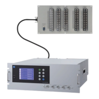
Fuji Electric FSC-4
195 pages
Fuji Electric Time Delta-C FSV-2
119 pages
Fuji Electric FLD-1
189 pages
Fuji Electric ZRE-2
85 pages
Fuji Electric NRF51
58 pages
Fuji Electric ZKJ Series
106 pages