2-5
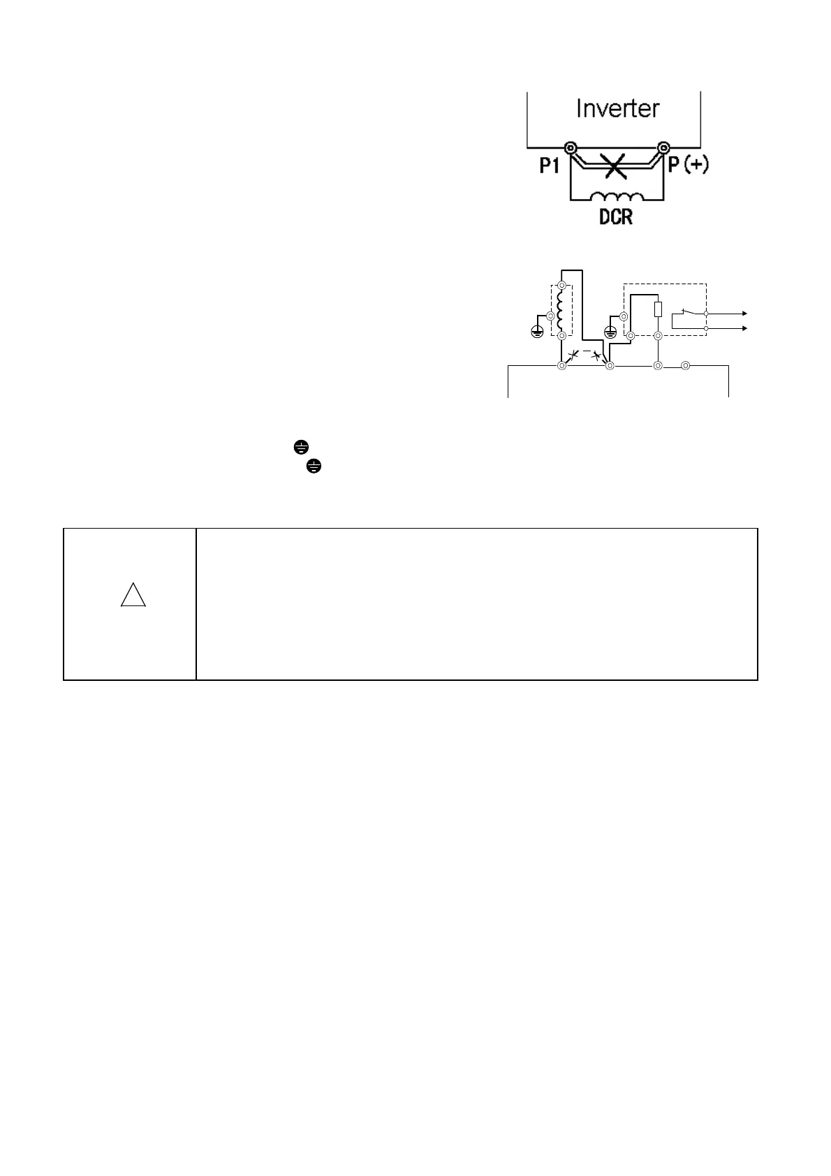
(3) DC reactor connecting terminals (P1, P (+))
a. Use this terminal to connect a DC reactor (option).
Remove the jumper connected in the factory before
connecting the DC reactor.
b. Do not remove the jumper if no DC reactor is used.
Cut the barrier in the main circuit terminal block cover
for the P1, P (+), DB and N (-) cable port using nippers
or the like when connecting wiring.
(4) External braking resistor connecting terminals (P (+), DB)
E11S is not equipped with a braking resistor. An external
braking resistor (option) is necessary for frequent
operation or heavy duty inertia load operation to
enhance the braking performance.
a. Connect the P (+) and DB terminals of the
external braking resistor to the P (+) and DB
terminals of the inverter.
b. Arrange devices so that the wiring length is within
5 m and twist or closely (in parallel) place the two
cables.
(5) Inverter grounding terminal (
G )
Ground the grounding terminal G for safety and noise reduction without fail. The metallic frame
of electrical equipment must be grounded in accordance with national or local electric code to
avoid electric shock, fire and other disasters.
!
!!
!
CAUTION
• Check that the number of phases and the rated voltage of the product agrees with
the number of phases and the voltage of the AC power supply.
• Do not connect the AC power cables to the output terminals (U, V, W).
Otherwise injuries could occur.
• Do not connect a braking resistor directly to the DC terminals (P (+), N (-)).
Otherwise fire could occur.
P1 P(+) DB N(-)
DC reactor
DCR
External braking resistor DB
P DB
2
1
(P24)
(THR)
Fig. 2-3-2 Connection diagram
Fig. 2-3-1 DCR connection diagram

 Loading...


