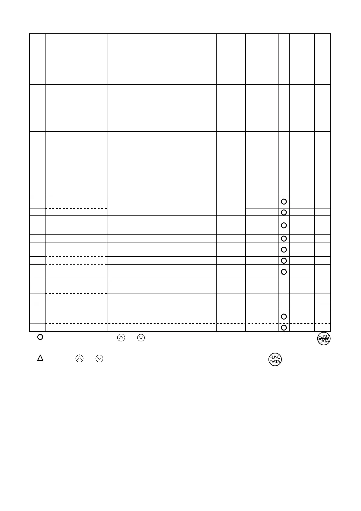
5-2
Function code
Name Setting range
Min.
unit
Factory
setting
RS485
Data
format
User setting
F13
Electronic thermal
overload relay
(for braking resistor)
0: Inactive
1: Active (for external braking resistor
DB__-2C/4C)
2: Active (for external braking resistor
TK80W : 0.1 to 2.2E11S-7
DB__-4C : 0.4 to 7.5E11S-4)
1 0
X
0
F14
Restart mode after
momentary power
failure
0:
Inactive (The inverter immediately
trips upon power failure.)
1: Inactive (The inverter trips afte
power failure is recovered.)
2:
Active (The inverter restarts at the
frequency effective at the time of
power failure.)
3:
Active (The inverter restarts at the
starting frequency.)
1 0
X
0
F15
Frequency limiter
(High)
70
0
F16
(Low)
0 to 400 Hz
1Hz
0
0
F17
Gain
(For frequency setting
signal)
0.0 to 200.0%
0.1% 100.0
2
F18
Bias frequency -400 to +400Hz
1Hz 0
1
F20
DC brake
(Starting frequency)
0.0 to 60.0Hz
0.1Hz 0.0
2
F21
(Braking level)
0 to 100%
1% 0
0
F22
(Braking time)
0.0 s (Inactive)
0.1 to 30.0s
0.1s 0.0
2
F23
Starting frequency
(Freq.)
0.1 to 60.0Hz
0.1Hz 0.5
X
2
F24
(Holding time)
0.0 to 10.0s
0.1s 0.0
X
2
F25
Stop frequency
0.1 to 6.0Hz
0.1Hz 0.2
X
2
F26
Motor sound
(Carrier frequency)
0.75,1 to 15kHz
1kHz 15
0
F27
(Sound tone)
0 to 3
1 0
0
: The data changed by the or key takes effect on the inverter operation. However, press the
key to store the new data.
: Press the or key to change the data. The new data takes effect after the key is pressed to
store the data.
X
: The data can be changed only while the inverter is stopped.

 Loading...


