5-3
Function code
Name Setting range
Min.
unit
Factory
setting
RS485
Data
format
User setting
F29
FMA and FMP
terminals
(Select)
0: Analog output (FMA)
1: Pulse output (FMP)
1 0
X
0
F30
FMA
(Voltage adjust)
0 to 200% 1% 100
0
F31
(Function)
0: Output frequency 1 (before slip
compensation)
1: Output frequency 2 (after slip
compensation)
2: Output current
3: Output voltage
4: Output torque
5: Load factor
6: Input power
7: PID feedback value
8: DC link circuit voltage
1 0
0
F33
FMP
(Pulse rate)
300 to 6000p/s (Pulse count at 100%)
1p/s 1440
0
F34
(Voltage adjustment)
0%, 1 to 200% 1% 0
0
F35
(Function)
0 to 8 (Same as F31)
1 0
0
F36
30Ry operation mode
0: Excited when tripping
1: Excited during regular operation
1 0
X
0
F40
Torque limiter 1
(Driving)
20 to 200%
999: Inactive
1% 180
0
F41
(Braking)
0%: Automatic deceleration control
20 to 200%
999: Inactive
1% 150
0
F42
Torque vector
control 1
0: Inactive
1: Active
1 0
X
0
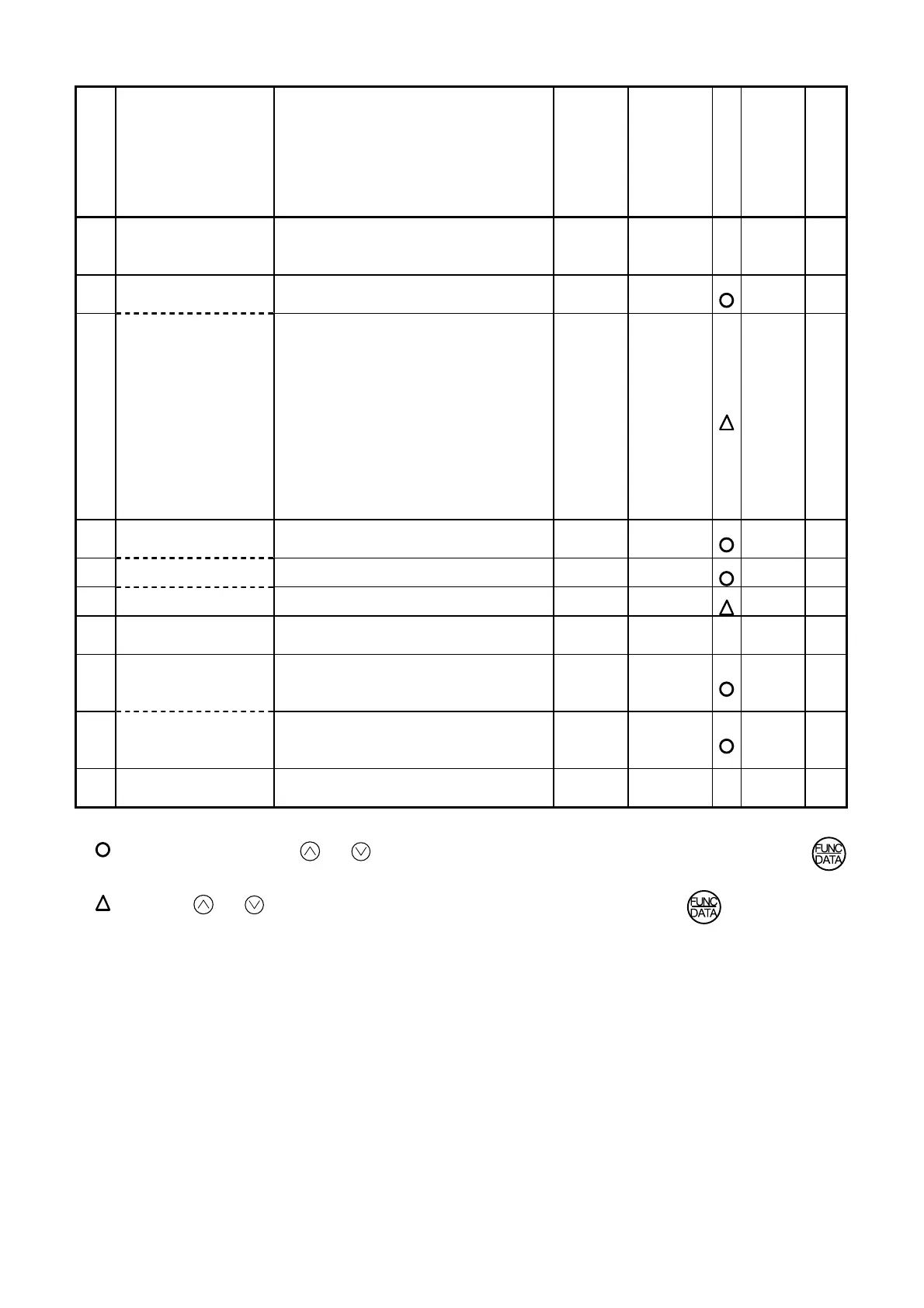
Description of change during operation
: The data changed by the or key takes effect on the inverter operation. However, press the
key to store the new data.
: Press the or key to change the data. The new data takes effect after the key is pressed to
store the data.
X
: The data can be changed only while the inverter is stopped.

 Loading...


