5-24
Torque polarity [B/D]
The polarity of the torque calculated inside the
inverter is judged and the driving/braking torque
discrimination signal is output.
When the calculated torque is the driving torque,
an OFF signal is output, and when it is the braking
torque, an ON signal is output.
Torque limiting [TL]
When the torque limit is set, a stall prevention
function automatically functions to change the
output frequency automatically; the torque limiting
signal is output externally to reduce the load or to
indicate an excessive load at the monitor.
The ON signal is output during torque limit,
regeneration avoidance operation and current
limit.
Auto restarting [IPF]
An event of momentary power failure, start-up of
restart mode after momentary power failure, and
automatic synchronization and recovery are
reported to the outside.
When the power is recovered and synchronization
starts after a momentary power failure, an ON
signal is output, and the signal changes to the
OFF signal after the frequency before the
momentary power failure is achieved.
In the startup at the starting frequency mode,
completion of restart is assumed at the time of
power recovery, and the signal is turned off in this
timing. (Refer to the description for F14.)
Overload early warning [OL]
An overload early warning level before thermal
protection trip (electronic thermal overload relay)
of the motor is judged and an ON signal is output.
Either the electronic thermal overload forecast or
output current overload forecast can be selected
for overload forecast judgement.
For the setting method, refer to Overload early
warning (Operation selection) (E33) and Overload
early warning (Operation level) (E34).
Note) This function is effective only for motor 1.
Life time alarm [LIFE]
Life judgement output for main circuit capacitor
Refer to section 8-2 (1) "Capacity measurement of
main circuit capacitor" for description.
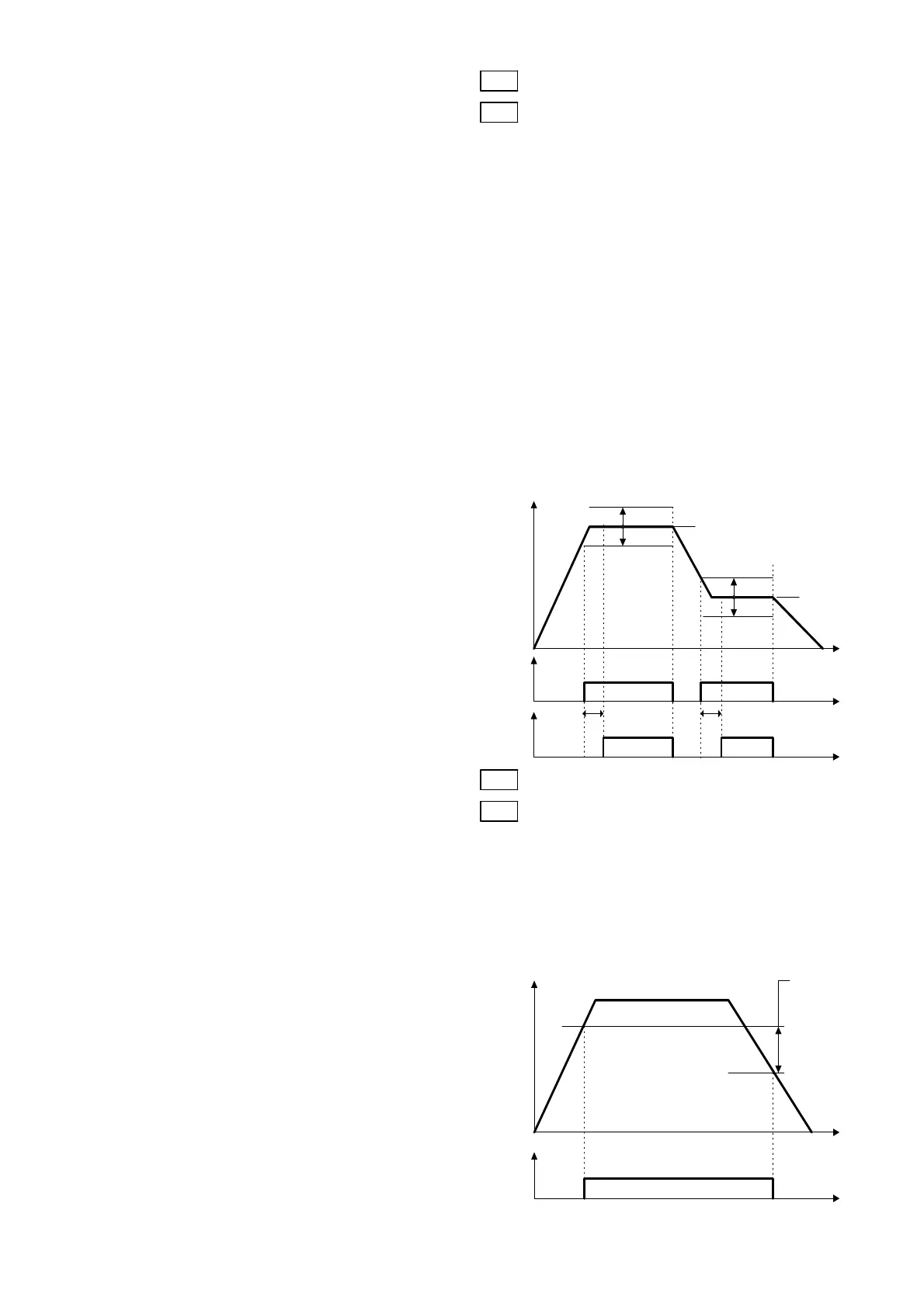
Frequency level detection 2 [FAR2]
This is a frequency level detection (detection
width) signal where function code E29 "Frequency
level detection delay" takes effect. Detection level
of the frequency is detected at the output
frequency before the torque limiter.
E29
Frequency level detection delay
E30 FAR function signal (Hysteresis)
Adjust the hysteresis and signal output delay for
achievement of the output frequency to the set
frequency (operation frequency).
The delay is valid only for FAR2 and it can be
adjusted between 0.01 and 10.0 seconds. The
hysteresis can be adjusted in a range of 0 to
+/-10 Hz of the output frequency.
The output frequency changes according to the
torque limiting operation. When the frequency
exceeds the setting range (width), the signal is
turned off in a mode (FAR: E20, 21 set to "1") or
it is not turned off in another mode (FAR2: E20,
21 set to "9").
E29: Setting range: 0.01 to 10.0 s
E30: Setting range: 0.0 to 10.0 Hz
An ON signal can be output from the terminal
within the detection range (width).
E31 FDT function signal (Level)
E32 FDT function signal (Hysteresis)
Determine the operation (detection) level of the
output frequency and the hysteresis width for
operation cancellation. When the output
frequency exceeds the set operation level, an
ON signal can be output from the terminal.
Setting range: (Operation level): 0 to 400 Hz
(Hysteresis width): 0.0 to 30.0 Hz
Output frequency
Frequency
detection
signal
Hysteresis width
Operation level
Cancellation level
Time
ON
Set frequency
Output frequency
FAR2
Time
ON ON
+ Detection width
- Detection
width
Set frequency
E29:Delay E29:Delay
+ Detection
width
- Detection
width
Set frequency
ON ON
FAR

 Loading...


