5-23
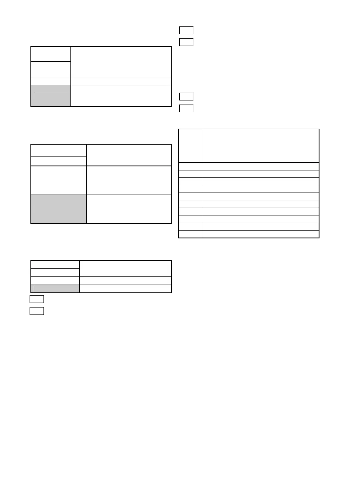
PID control cancel [Hz/PID]
An external digital input signal can disable PID
control.
Input
signal
16
[Hz/PID]
Selected function
off
PID control valid
on
PID control invalid
(frequency setting through keypad
panel)
Inverse mode changeover(Terminal 12 and
C1) [IVS]
An external digital input signal switches between
the forward and reverse operations of analog
inputs (terminals 12 and C1).
Input signal
17[IVS]
Selected function
off
When forward operation is set
→forward operation
When reverse operation is set
→reverse operation
on
When forward operation is set
→reverse operation
When reverse operation is set
→forward operation
Link enable (RS485) [LE]
An external digital input signal is switched to
validate or invalidate the frequency command and
operation command from the link. The source of
the command can be set at H30 Link function.
Input signal
18[LE]
Selected function
off
Link command invalid
on
Link command valid
E10 Acceleration time 2
E11 Deceleration time 2
◆ Additional acceleration and deceleration time
can be selected besides F07 "Acceleration time
1" and F08 "Deceleration time 1".
◆ The operation and setting range are the same
as those for F07 "Acceleration time 1" and F08
"Deceleration time 1". Refer to these functions.
◆ To switch between the acceleration and
deceleration time, select any terminal from
among E01 "X1 terminal (Function selection)"
through E05 "X5 terminal (Function selection)"
as a switching signal input terminal. Set the
selected terminal to "4"
(acceleration/deceleration time selection) and
supply a signal to the terminal to switch.
Switching is effective during acceleration,
during deceleration or during constant speed
operation.
E16 Torque limiter 2 (Driving)
E17 Torque limiter 2 (Braking)
◆ Use these functions to switch the torque limiter
levels set at F40 and F41 using an external
control signal. The external signal is supplied to
an arbitrary control terminal among X1 through
X5, the function of which is set to torque control
2 / torque control 1 (data 12) at E01 to E05.
E20 Y1 terminal function
E21 Y2 terminal function
◆ A part of control and monitor signals can be
output at the Y1 and Y2 terminals.
Setting
Output signal
0 Inverter running [RUN]
1 Frequency equivalence [FAR]
2 Frequency level detection [FDT]
3 Undervoltage detection signal [LV]
4 Torque polarity [B/D]
5 Torque limiting [TL]
6 Auto restarting [IPF]
7 Overload early warning [OL]
8 Life time alarm [LIFE]
9 Frequency level detection 2 [FAR2]
Inverter running [RUN]
"Inverter running" means that the inverter outputs
a frequency as a speed signal. At this time, an ON
signal is output. However, if the DC braking
function is active, the signal is turned off.
Frequency equivalence [FAR]
Refer to the description for function code E30
Frequency equivalence (detection width).
Frequency level detection [FDT]
Refer to the description for function codes E31
and E32 Frequency level detection.
Undervoltage detection signal [LV]
When the undervoltage protection function is
active, that is, when the main circuit DC voltage is
below the undervoltage detection level, an ON
signal is output. After the voltage is restored to
become higher than the undervoltage detection
level, the signal is turned off. The ON signal is
output also during activation of the undervoltage
protection function.
Undervoltage detection level: Approx 200 Vdc
(200V class)
: Approx 400Vdc
(400V class)

 Loading...


