5-22
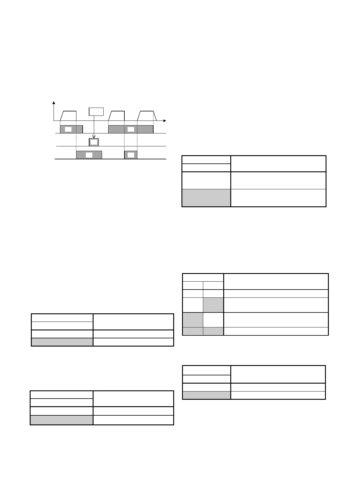
Coast-to-stop command [BX]
When the BX terminal is connected to the P24
terminal, the inverter output is immediately shut off
and the motor coasts to stop. No alarm signal is
output. This signal is not maintained.
When the operation command (FWD or REV) is
ON and the BX terminal is disconnected from the
P24 terminal, the motor starts at the starting
frequency.
Forward
ON
ONON
ONON
FWD-CM
REV-CM
BX-CM
Output
frequency
Ignored
Forward
Forward
Alarm reset [RST]
Upon tripping, when the connection between the
RST and P24 terminals is turned on, the batch
alarm output is removed, and when the connection
is turned off, the trip display is removed and
operation is restarted.
Trip command (External fault) [THR]
When the connection between the THR and P24
terminals is turned off, the inverter output is shut
off (to allow the motor to coast to stop), and an
alarm [OH2] is output. This signal is maintained
internally until an RST input is added. This
function is used to protect the external braking
resistor from being overheated. When this terminal
function is not set, an ON input is assumed.
Frequency setting 2/1 [Hz2 / Hz1]
An external digital input signal switches the
frequency setting method defined by function
codes F01 and C30.
The signal operation is changed under PID control.
(Refer to H20 through H25.)
Input signal
9[Hz2/Hz1]
Selected frequency setting
off
F01 Frequency setting 1
on
C30 Frequency setting 2
Motor 2/1 [M2 / M1]
An external digital input signal switches each
motor constant. However, this input is effective
only when the operation command to the inverter
is turned off and the inverter is stopped. Therefore
operation at 0 Hz is not included.
Input signal
10[M2/M1]
Selected motor
off
Motor 1
on
Motor 2
DC brake command [DCBRK]
When the external digital input signal is ON, DC
braking starts and continues as far as the signal
remains turned on after the operation command is
turned off (or, the STOP key is pressed in the
keypad panel operation mode or both the FWD
and REV terminals are turned on or turned off in
the terminal block operation mode) and the
inverter frequency drops below the frequency set
at F20. In this case, the longer time between the
time set at function code F22 and the time when
the input signal is turned on, is given priority.
However, operation is restarted if the operation
command is turned on.
Torque limiter 2/Torque limiter 1 [TL2 / TL1]
An external digital input signal switches between
the torque limiter values set at function codes F40
and F41 or E16 and E17.
Input signal
12[TL2/TL1]
Selected torque limit value
off
F40 Torque limiter 1 (Driving)
F41 Torque limiter 1 (Braking)
on
E16 Torque limiter 2 (Driving)
E17 Torque limiter 2 (Braking)
UP command [UP] / DOWN command
[DOWN]
The output frequency can be increased or
decreased according to the external digital input
signal while the operation command is input
(turned on). The changing range is 0 to the
maximum output frequency and operation in a
direction opposite to that in the operation
command is impossible.
Input signal
13 14
Selected function
(when operation command is ON)
off off
The output frequency is maintained.
off on
The output frequency increases at
the acceleration time.
on off
The output frequency decreases at
the deceleration time.
on on
The output frequency is maintained.
Write enable for KEYPAD [WE-KP]
This function allows program changes only while
the external signal is input; this is for the protection
of the program from inadvertent changes.
Input signal
15[WE-KP]
Selected function
off
Data change disabled
on
Data change enabled
Note) If data 15 is set to a terminal erroneously,
program change become disabled. Turn the
terminal ON then change to another number.

 Loading...


