5-28
C21
Timer operation
C22 Stage 1
An operation pattern from the start of
operation to automatic stop can be created.
C21
Select active or inactive timer operation.
0: Inactive timer operation
1: Active timer operation
C22
Set the time from the start of operation to
automatic stop.
Setting range: 0.00 to 3600 s
Note) If the power is turned off or the inverter is
stopped or trips during timer operation, the
counted time is reset.
C30 Frequency command 2
Select the frequency setting method.
For the selectable frequency setting methods,
refer to the description of F01.
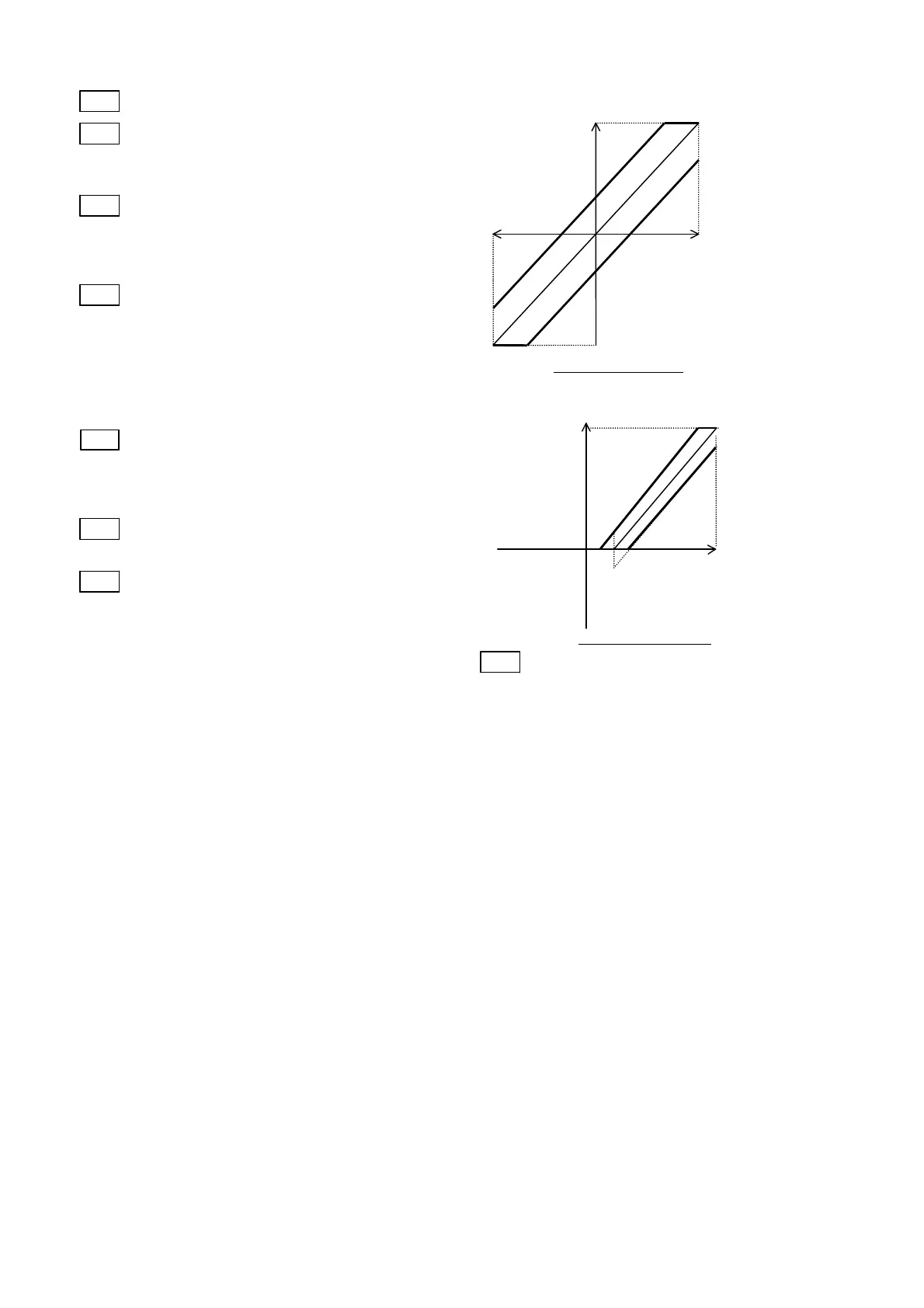
C31 Analog setting signal offset
adjustment (Terminal 12)
C32 Analog setting signal offset
adjustment (Terminal C1)
Set the offset of the analog input (terminal [12],
terminal [C1]).
The offset can be set in the range between -5.0
[%] and + 5.0 [%] of the maximum output
frequency (in 0.1 [%] step).
Frequency setting
Maximum
output
frequency
Frequency setting
voltage input
Terminal【
】
+ 5%
-5%
-10V
+10V
Maximum
output
frequency
Frequency setting
current input
Frequency setting
Terminal【
】
+ 5%
-5%
0
20mA
C33 Analog setting signal filter
The analog signal supplied to control terminal
12 or C1 sometimes includes electric noise.
Electric noise make the control unstable. Adjust
the time constant of the input filter to remove
the effects of electric noise.
Setting range: 0.00 to 5.00 s
With a large time constant (setting), the control
becomes stable but there is a delay in the
control response. With a small time constant,
the response is quick but the control becomes
unstable.
If the setting is not clear, change the setting
when the control is unstable or the response is
slow.
Note) The function applies to both terminals [12]
and [C1] (in common). However, when a
PID feedback signal is input, H25 "PID
control feedback filter" is applied.
20mA

 Loading...


