2 - 1
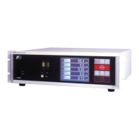
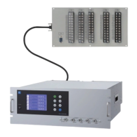
2.1 Name and description of analyzer main unit
2. NAME AND DESCRIPTION OF EACH UNIT
Fig. 2-1
Name 'HVFULSWLRQ Name 'HVFULSWLRQ
(1) Handle 8VHGIRUZLWKGUDZLQJWKHPDLQ
unit from the panel.
/LJKWVRXUFH
cover
Infrared light source is arranged
in the cover.
(2) Power switch 8VHGIRU212))WKHDQDO\]HU &RQQHFWRUWR
input/output
terminal module
For connecting to the external
input/output terminal module
'LVSOD\RSHUDWLRQ
panel
/LTXLGFU\VUDOGLDSOD\DQGNH\V
for setting various functions
3RZHULQOHW For connecting the power cord
(4) Sampling gas
inlet
For connecting to the measuring
gas tube
(10) Protective cover Protective cover for the light
VRXUFHDQGWKHPRWRU0D\EH
removed during operation.
(5) Sampling gas
outlet
&RQQHFWWRWKHH[KDXVWOLQH$
pair of sampling gas inlet/outlet
is provided for each measuring
unit.)
(11) Fuse holder 97$/
(6) Sector motor For driving the rotation of sector (12) Purge gas inlet
For purging the inside of the total
gas analyzer
(1) Handle
(2) Power switch
(5) Sampling gas outlet
(4) Sampling gas inlet
(12) Purge gas inlet
(4) Sampling gas inlet
(3) Display/operation panel
For measuring
unit 1
For measuring
unit 2
(6) Sector motor
(7) Light source cover
(9) Power supply receptacle
(11) Fuse holder
(5) Sampling gas outlet
(8) Connector to input/output terminal module
<Front panel>
<Back panel>
(10) Protective cover
I
I
80
80
80
e9
[
I
}
}
'
 Loading...