9 - 1
9. SPECIFICATIONS
*HQHUDOVSHFL¿FDWLRQV
SPECIFICATIONS
6WDQGDUG6SHFL¿FDWLRQV
Measurement principle:
NO, SO
2, CO2, CO, CH4, N2O:
Non-dispersive infrared (NDIR) method,
Single light source and double beams (double-beam
system)
O
2:
Built-in paramagnetic O
2 sensor or external zirconia
O
2 analyzer
Measurable gas components and measuring range:
Minimum range Maximum range
NO 0–50 ppm 0–5000 ppm
SO
2
0–50 ppm 0–10 vol%
CO
2
0–20 ppm 0–100 vol%
CO 0–50 ppm 0–100 vol%
CH
4
0–200 ppm 0–100 vol%
N
2
O 0–200 ppm 0–2000 ppm
O
2
(built in) 0–5 vol% 0–25 vol%
O
2
(External Zirconia) 0–5 vol% 0–25 vol%
0D[FRPSRQHQWVPHDVXUHPHQWLQFOXGLQJ22.
0HDVXULQJUDQJHUDWLR2
2)
H[FHSWIRU2
2)
0HDVXULQJUDQJHVDUHFKDQJHDEOHEHWZHHQWKHVSHFL
¿HGPLQLPXPDQGPD[LPXPUDQJH
Settable 1 range or 2 ranges.
,I\RXPHDVXUH1
2O only, do not let any other compo-
nents be included in the sample gas.
If you measure multiple components including N
2O,
the measurement ranges of N
22 DUH ¿[HG WR ±
ppm and 0–500 ppm. If the measuring objects are N
2O
and CO
2, the measurement ranges of CO2DUH¿[HGWR
0–10% and 0–20%.
* For measurable components and possible combinations
of measuring ranges, refer to Section 9.3 (1) - (8).
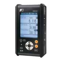
Measured value indication:
Digital indication in 4 digits (LCD with LED back light)
,QVWDQWDQHRXVYDOXHRIHDFKFRPSRQHQW
,QVWDQWDQHRXVYDOXHDIWHU2
2 conversion
(only in NO, SO
2, CO measurement with O2)
$YHUDJHYDOXHDIWHU2
2 conversion
(only in NO, SO
2, CO measurement with O2)
2
2 average value
Analog output signals:
* Inputs/outputs of analog signals are possible by com-
bining with the input/output terminal module.
WRP$ '& RU WR 9 '& LVRODWHGLQWHUQDOO\IURP
circuit and ground. Output lines are non-isolated each
other; 12 points max.
PD[ORDGIRUWRP$'&
PLQORDGNIRUWR9'&
* Refer to 5.3 (3) Contents of measured channel (Ch)
for channel allocation for each component.
Analog input signal:
Signal from external O
2 analyzer;
(1) Signal from Fuji zirconia O
2 analyzer (ZFK7)
WR9'&IXOOVFDOHVLJQDO
,QSXWVHFWLRQLVQRLVRODWHG
([WHUQDO2
2 analyzer is a separate order item.
Relay contact output:
DFRQWDFW9$&$UHVLVWLYHORDG
,QVWUXPHQWHUURUFDOLEUDWLRQHUURUUDQJHLGHQWL¿FDWLRQ
auto calibration status, pump ON/OFF, peak alarm.
1c FRQWDFW 9$&$ UHVLVWLYH ORDG VHOHFWDEOH
outputs)
High/Low limit alarm contact output.
Power disconnection alarm.
$OOUHOD\FRQWDFWVDUHLVRODWHGPXWXDOO\DQGIURPWKH
internal circuit.
Contact input:
1RYROWDJH FRQWDFW 219 2))9 '& P$ ÀRZLQJ
at ON)
Remote range switch, auto calibration remote start, re-
mote holding, average value resetting, pump ON/OFF
Isolated from the internal circuit with photocoupler.
Contact inputs are not isolated from one another.
Transmission output:
Solenoid valve drive signal for automatic calibration.
7UDQVLVWRURXWSXWP$RUOHVV
Power supply:
9ROWDJHUDWLQJ9WR9$&
$OORZDEOHUDQJH9WR9$&
Frequency ; 50Hz/60Hz
3RZHUFRQVXPSWLRQ9$PD[
Inlet; Conform to EN60320, Protection Class 1
Operating conditions:
$PELHQWWHPSHUDWXUH&WR&
$PELHQWKXPLGLW\5+PD[QRQFRQGHQVLQJ
Storage conditions:
$PELHQWWHPSHUDWXUH&WR&
$PELHQWKXPLGLW\5+PD[QRQFRQGHQVLQJ
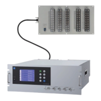
Dimensions (H x W x D):
$QDO\]HUPDLQXQLWîîPP
,QSXWRXWSXWWHUPLQDOPRGXOHîîPP
Mass:
$SSUR[NJRQO\$QDO\]HU
Finish color:
Front panel; Light gray (Munsell N7.2 or equivalent)
Casing; Plating, Steel-blue (gray)
Enclosure:
Steel casing, for indoor use
Material of gas-contacting parts:
Gas inlet/outlet/purging; SUS304 or resin
Sample cell; SUS304,chloroprene rubber
Infrared-ray transmitting window; CaF
2
O2 sensor sample cell : SUS316
Internal piping; vinyl chloride, PTFE, Polypropylene
Gas inlet/outlet:
Rc1/4 or NPT1/4 internal thread
3XUJHJDVÀRZUDWH
1L/min (when required)
Standard Functions
Output signal holding:
Enables you to hold the output signal during calibration
to the value right before the calibration is started or the
XVHUVSHFL¿HGYDOXH9DOXHVLQGLFDWHGRQ/&'ZLOOQRW
be held.
 Loading...