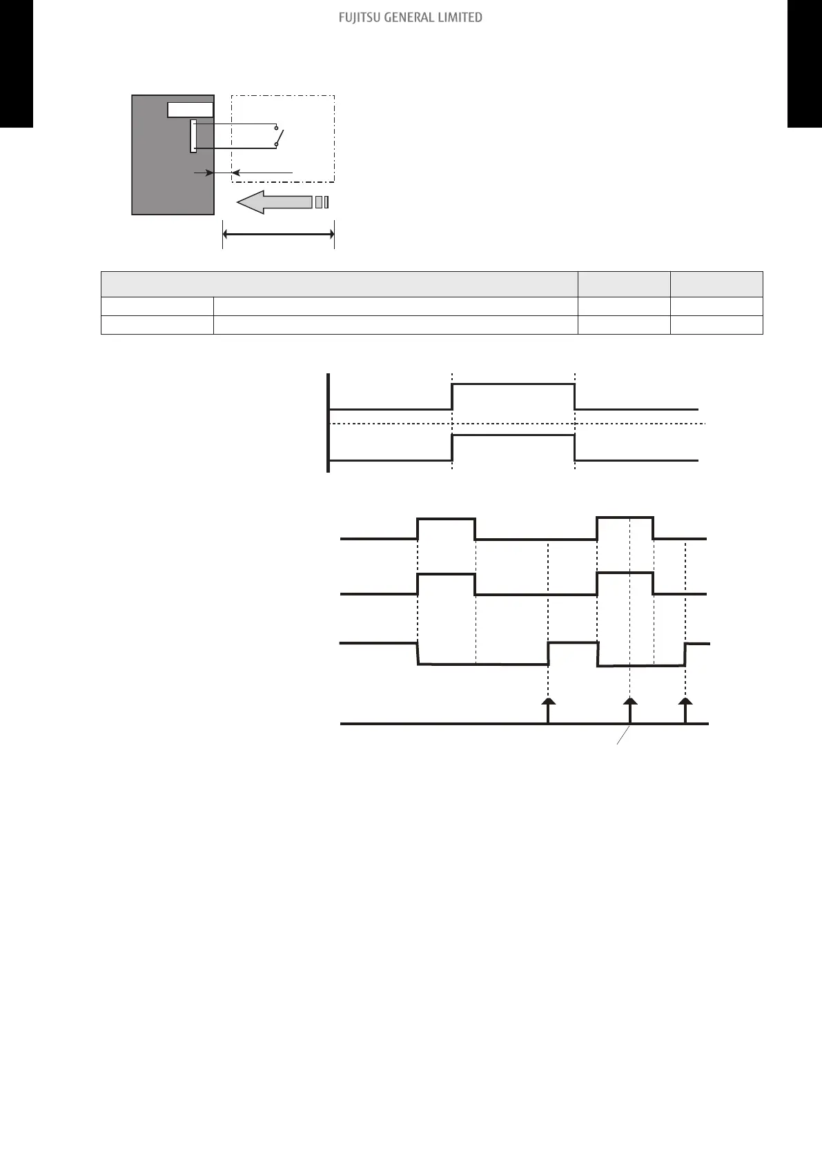
• Circuit diagram example
Indoor unit
control PCB
*1
Example: Switch
Locally purchased
Connected unit
1
3
Signal
Connector
33 ft. (10 m)*2
• Contact capacity: DC 24 V or more, 10 mA or more.
• *1: PCB of Communication kit is used for wall mounted
(ASU7RLF1, ASU9RLF1, ASU12RLF1, and
ASU15RLF1) type.
• *2: Make the distance from the PCB to the connected
unit within 33 ft (10 m).
• Use non-polar relays and switches.
Indoor unit type 1-pin 3-pin
Wall mounted ASU7RLF1, ASU9RLF1, ASU12RLF1, ASU15RLF1 - +
Floor AGU9RLF, AGU12RLF, AGU15RLF - +
– When function setting is "Operation/Stop" mode
Operation
Stop
On
Off
Input signal
Indoor unit
– When function setting is "Forced stop" mode
Remote controller
On On On
Input signal
Indoor unit
Command
Remote control
operation invalidity
On
Off
Operation
Stop
Forced stop
Normal
- 121 -
12-1. External input 12. External input and output (RLF1 series wall mounted type and floor type indoor unit)
MULTI-SPLIT TYPE
5-unit type
MULTI-SPLIT TYPE
5-unit type
 Loading...