4-6. IPM on transistor PCB
Check point 1
1 Disconnect the connection wires between the transistor PCB—capacitor
PCB and transistor PCB—inverter PCB.
2 Set the tester to the resistance mode, and measure the resistance between the following termi-
nals.
TM301 (P)—TM305 (U)/TM304 (V)/TM303 (→)
TM302 (N)—TM305 (U)/TM304 (V)/TM303 (→)
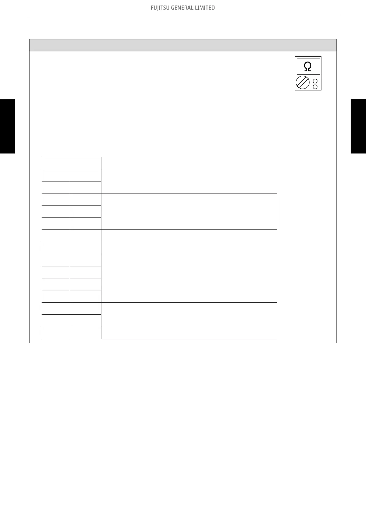
3 Judge the result of 2 as follows:
Terminal
Resistance valueTester
(+) (-)
P U
Over 2 kΩ (Including ∞ Ω)P V
P →
U P
Over 20 kΩ (Including ∞ Ω)
V P
→ P
N U
N V
N →
U N
Over 2 kΩ (Including ∞ Ω)V N
→ N
4-6. IPM on transistor PCB - (03-52) - 4. Service parts information
TROUBLESHOOTING
TROUBLESHOOTING
 Loading...