8-3. Combination of external input and output
By combining the function setting of the indoor unit and rotary switch setting of the External input
and output PCB, you can select various combinations of functions.
Combination examples of external input and output are as follows:
Mode
External input
and output PCB
(Rotary SW)
External input
External input and output PCB
CN313 CN314 Signal type
0-1 1
Operation/Stop Not available Edge
Operation Stop Pulse
0-2 2 Forced Thermostat OFF Not available Edge
1—8 3 - 9, A (Setting prohibited)
9 B Forced Thermostat OFF Not available Edge
10 C Forced Thermostat OFF Not available Edge
11 D Forced Thermostat OFF Not available Edge
Mode
External input
and output PCB
(Rotary SW)
External output
External input and output PCB
CN310 CN311 CN312
0-1 1 Operation/Stop Error status
Indoor unit fan operation
status
0-2 2 Error status
Indoor unit fan operation
status
Not available
1—8 3 - 9, A (Setting prohibited)
9 B Operation/Stop
Indoor unit fan operation
status
Not available
10 C Operation/Stop Error status Not available
11 D Operation/Stop
Indoor unit fan operation
status
Error status
NOTE: Input of Operation/Stop depends on the setting of function setting 46.
00: Operation/Stop mode 1 (R.C. enabled)
01: (Setting prohibited)
02: Forced stop
03: Operation/Stop mode 2 (R.C. disabled)
¢
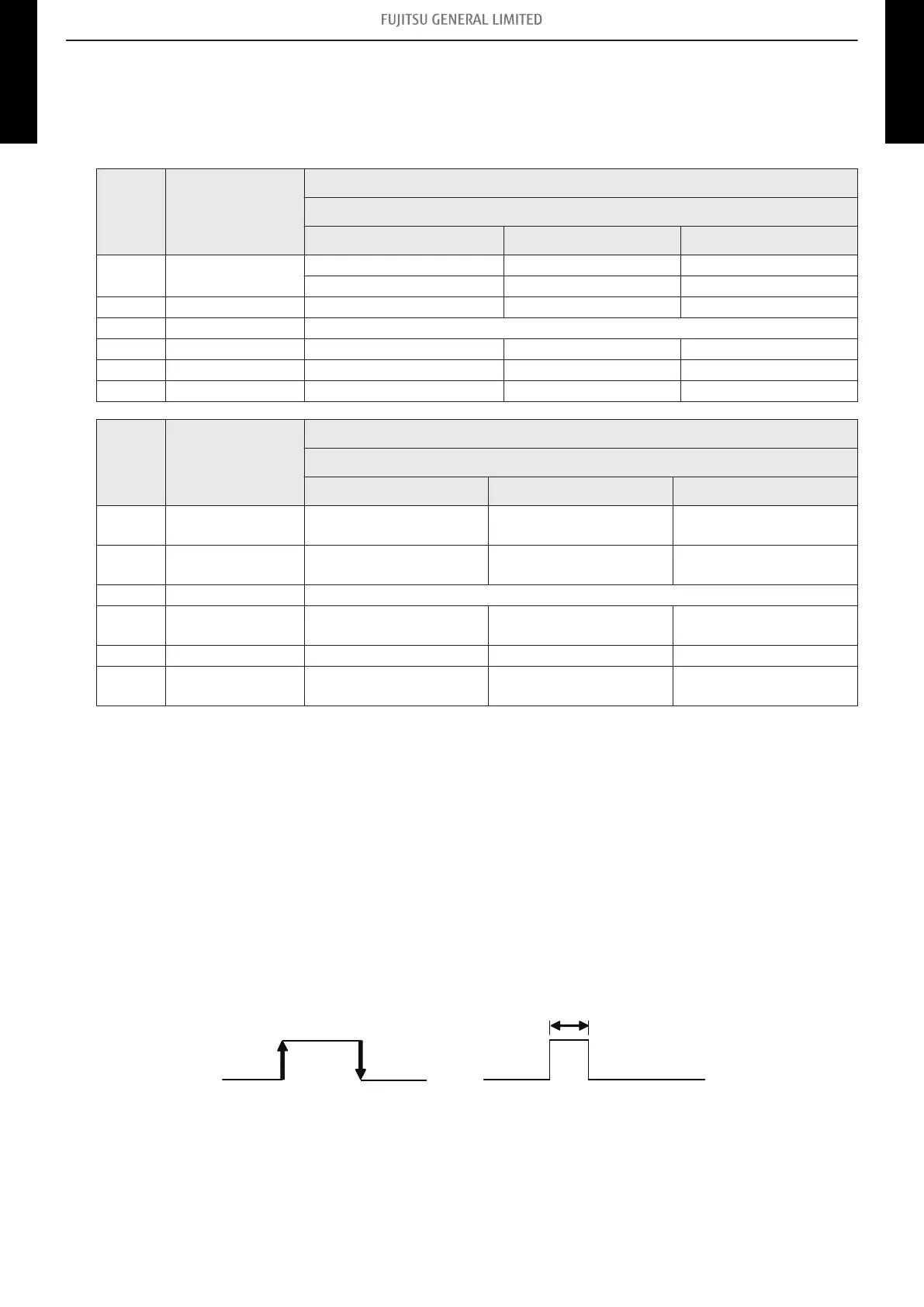
Input signal type
External input and output PCB:
The input signal type can be selected.
Signal type (edge or pulse) can be switched by the DIP switch SW302 on the External input and out-
put PCB.
Pulse
The width of pulse must be
longer than 200 msec.
Edge
- 20 -
8-3. Combination of external input and output 8. External input and output
WALL MOUNTED
ASYG09-14KMCDN
WALL MOUNTED
ASYG09-14KMCDN
 Loading...