Mainboard D2778 English - 21
Fujitsu Technology Solutions 21
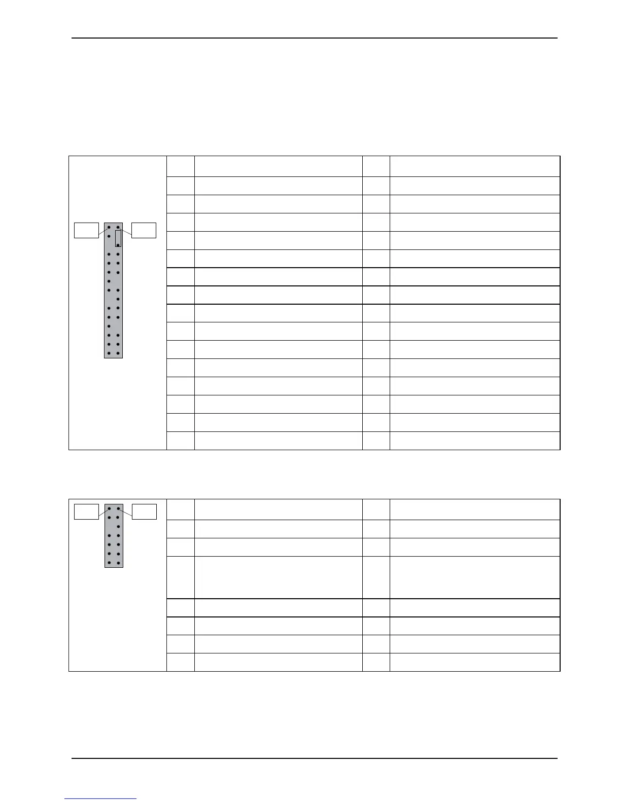
Frontpanel Connector (internal)
Normally, a chassis has some control or signal wires can be connected onto a motherboard for hard
drive LED, Power LED, power button, and reset button;
The front panel connector has been implemented on D2778 for such purposes.
PIN Signal PIN Signal
1 GND 2 Speaker -
3 Not connected 4 Key
5 Key 6 GND
7 PowerON LED + 8 Speaker +
9 PowerON LED + 10 Reserved
11 PowerON LED - GND 12 Reserved
13 Not connected 14 Key
15 Not connected 16 Password Skip
17 Key 18 GND (1K)
19 HD LED + 20 GND (1K)
21 HD LED - 22 Recover BIOS
23 GND 24 Key
25 Power-Button (low asserted) 26 GND
27 Reserved 28 GND
Pin 2
Pin 1
29 Reset-Button (low asserted) 30 GND
LCD connector (internal)
PIN Signal PIN Signal
1 SMB CLK 2 GND
3 SMB DATA 4 GND
5 Key 6 A-Version: Not Connected
B-Version: USB Dynamic
Security
7 LAN Activity Icon 8 LAN Link Icon
9 Harddisk Action Icon 10 BMC Alert Icon
11 Not connected 12 Sleep Icon
Pin 2
Pin 1
13 Power Icon 14 P3V3P DUAL (polyswitch fused)