7
FUJITSU Storage ETERNUS DX100 S3/DX200 S3 Hybrid Storage Systems Setup Guide
Copyright 2017 FUJITSU LIMITED
P3AM-7852-06ENZ0
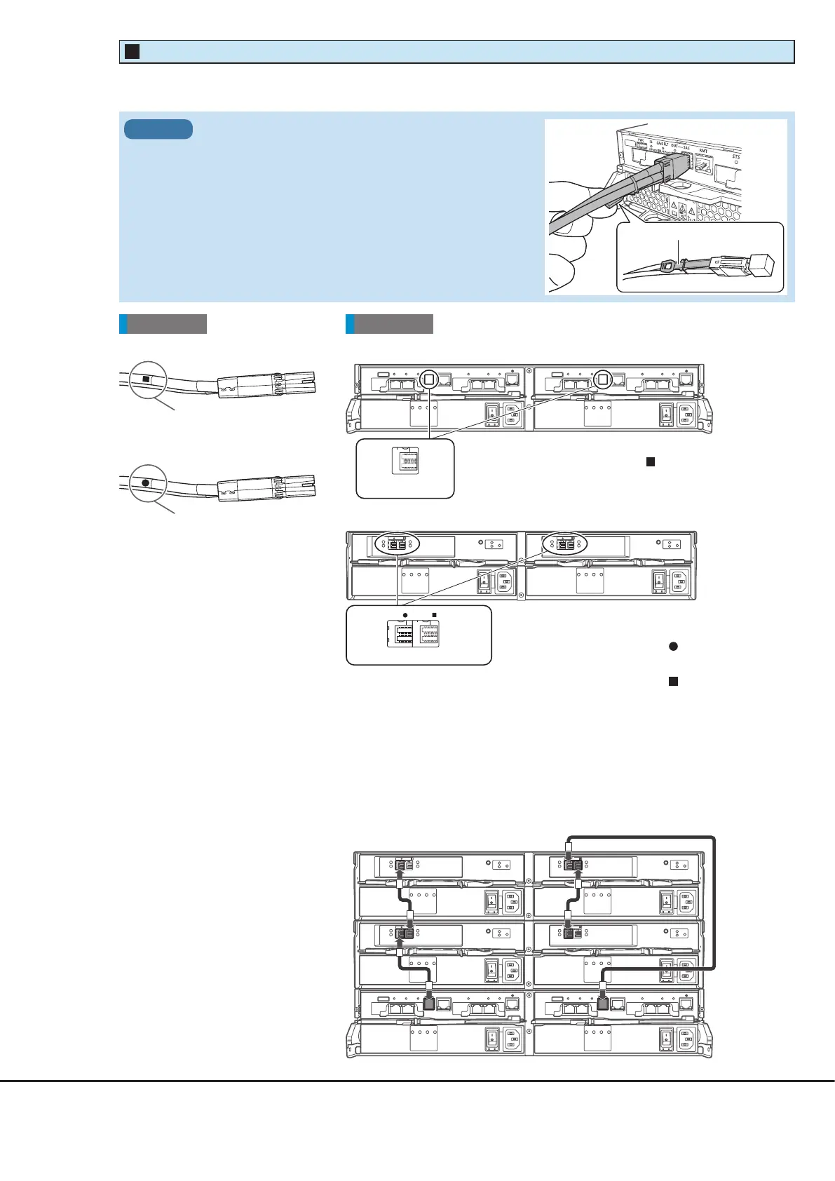
DI (OUT) portDI (IN) port
●
DI (OUT) side plug
●
DI (IN) side plug
Rear viewCable
Attach the destination labels
to the plugs of the mini SAS HD
cables between enclosures.
When drive enclosures are installed, use mini SAS HD cables between enclosures to connect between the DI ports of
each enclosure.
●
Controller enclosure
●
Drive enclosure
●
Example of mini SAS HD cable connections between enclosures
(when two drive enclosures are installed)
Between Controller 0 and I/O module line 0, connect the drive enclosures
in ascending order of the drive enclosure numbers.
Between Controller 1 and I/O module line 1, connect the drive enclosures
in descending order of the drive enclosure numbers.
The DI (IN) port is on the left side and the DI (OUT) port is on
the right side of each I/O module.
Plug the connectors on which the "
" symbol is printed into
the DI (IN) ports.
Plug the connectors on which the "
" symbol is printed into
the DI (OUT) ports.
The " ■ " symbol is
The "●" symbol is
printed here.
DI (OUT) port
The controller enclosure only has DI (OUT) ports.
Connect the connectors on which the "
" symbol is printed.
Controller enclosure
Drive enclosure 2
Drive enclosure 1
Mini SAS HD Cable Between Enclosures
3
When connecting the mini SAS HD cable between enclosures,
check the direction of the connector (the tab must be pointed
downward) and firmly insert all the way in.
IMPORTANT
Tab