3-1. External input
• “Operation/Stop” mode or "Forced stop" mode can be selected with function setting of indoor unit.
• A twisted pair cable should be used. Maximum length of cable is 150 m.
• Use an external input and output cable with appropriate external dimension, depending on the
number of cables to be installed.
• The wire connection should be separate from the power cable line.
¢
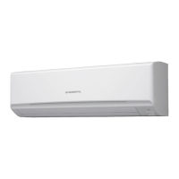
Indoor unit
Indoor unit functions such as Operation/Stop can be done by using indoor unit terminals.
*1: The switch can be used on the following condition: DC 12 V to 24 V, 1 mA to 15 mA.
¢
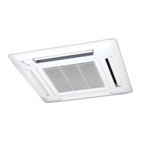
External input and output PCB
The indoor unit Operation/Stop can be set by using the input terminal on the PCB.
• Input select
Use either one of these types of terminals according to the application. (Both types of terminals
cannot be used simultaneously.)
– Dry contact
In case of internal power supply, set the slide switch of SW1 to "NON VOL" side.
Input 1 Input 2
Ex IN
Connected device
*1 *1
+
+
-
*1: The switches can be used on the following condition: DC 12 V to 24 V, 1 mA to 15 mA.
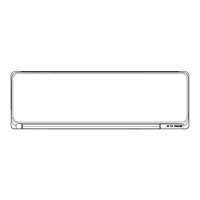
– Apply voltage
In case of external power supply, set the slide switch of SW1 to "VOL" side.
Input 1 Input 2 Power supply
Ex IN
Connected device
*1 *1
*2
+-
*1: The switches can be used on the following condition: DC 12 V to 24 V, 1 mA to 15 mA.
*2: Make the power supply DC 12 V to 24 V, 10 mA or more.
3-1. External input
- (05-12) - 3. External input and output (For indoor unit)
FIELD
WORKING
FIELD
WORKING
 Loading...