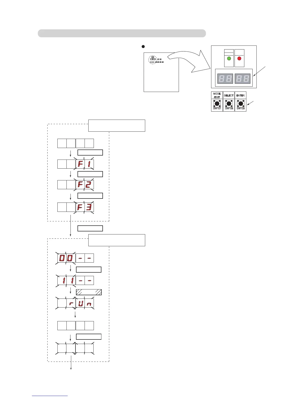
SWITCH POSITION
SW107 SW108 SW109
MODE
/EXIT
SELECT ENTER
LED101
(GREEN)
POWER
MODE
LED105 LED104
LED102
(RED)
ERROR
Push button switch
7 Segment
LED Lamp
Outdoor unit printed circuit board
Check that the rotary switch IU AD on the indoor unit
Main PCB is set to “00”. If it is not set to “00”,
it means the address of that device is not set.
(Factory default is “00”).
Turn on the power of the indoor and outdoor units.
When the system is normal, nothing will be displayed
on the 7 segment display.
When ERROR is displayed, inspect the units.
Use the “MODE/EXIT”, “SELECT”, and “ENTER” buttons
on the outdoor unit Main PCB to configure settings
according to the procedures below.
1: FUNCTION Setting
First 2 digits Last 2 digits
(the display when the main power is turned on)
(When [F4] to [F9] are displayed, continue to press the “SELECT” button until [F3] is displayed.)
M
SELECT
SELECT
ENTER
It may take about 10 minutes for completing the processing.
End
First 2 digits Last 2 digits
Press the “SELECT” button until “11” is displayed.
Press the “ENTER” button for more than 3 seconds.
Automatic address setting
for indoor units
The number of indoor units with normal settings will be displayed at the first 2 digits of
the 7 segment display.
The number of indoor units with error will be displayed at the last 2 digits.