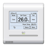
Branch box
(Primary)
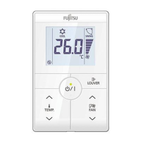
REMOTE
CONTROL
Branch box
(Secondary 1)
REMOTE
CONTROL
Branch box
(Secondary 2)
REMOTE
CONTROL
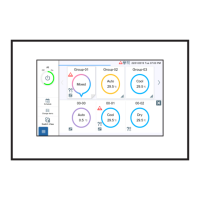
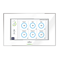
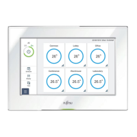
Central remote controller
Remote controller cable
• Total remote controller cable length:
MAX. 500 m
5.3. Installation
WARNING
• Always use the accessories and specified installation work parts.
Check the state of the installation parts. Not using the specied parts
will cause units to fall off, water leakage, electric shock, re, etc.
• When installing this unit, make sure that there are no children nearby.
Otherwise, injury or electric shock could result.
• After installing this unit, perform the test run to conrm that the unit
is operating properly. Then, explain the operation of this unit to the
customer.
CAUTION
• Do not set the DIP switch of this unit except as specified in this
installation manual or the installation manual supplied with the air
conditioner. Setting the switches other than specified will cause an
accident or trouble.
• Use an insulated screwdriver to set the DIP switches.
• Before opening the case of this unit, completely discharge static
electricity charged on your body. Not doing so will cause trouble.
• Do not touch the circuit board and circuit board parts directly with your
hands. Otherwise, injury or electric shock could result.
• Tightening the mounting screws too tight will damage the case of this
unit.
• Be careful so that the front cover does not fall after the front cover are
removed. Otherwise, injury could result.
(1) Remove the insulation of the remote controller cable.
Unit : mm
1. 12V (Red)
2. Signal (White)
3. COM (Black)
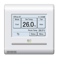
(2) Insert the at-blade screwdriver and remove the front case and rear
case by twisting it slightly.
Flat screwdriver
Front case
Hooks (2 places)
Rear case
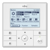
(3) Install the rear case to the wall, box, etc. with 2 screws (M4 × 16 mm).
Fix the 2 screws in either horizontal or vertical position.
A. When mounting on the box:
• Attach the case after leading the cable.
Screws
Box
Remote controller cable
Rear case
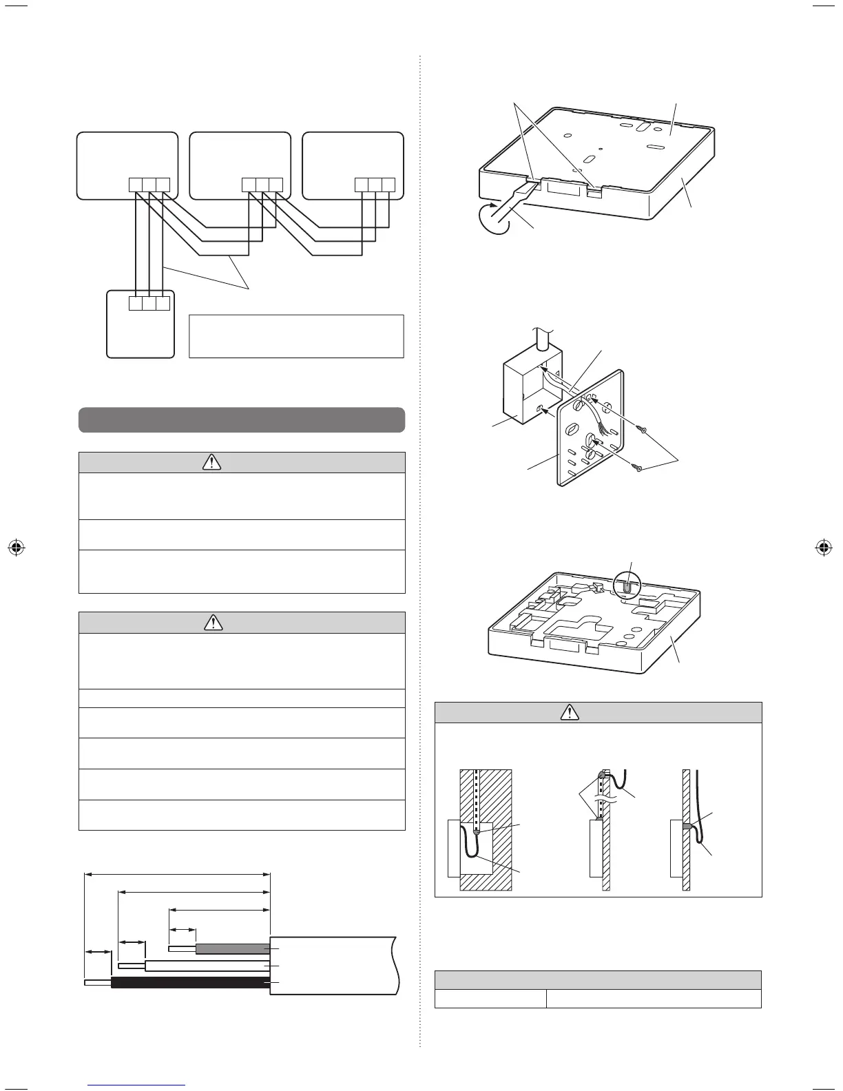
B. When the cable is along the wall:
• Mount the rear case on the wall.
• Cut off a hole for cabling in the front case.
Front case
Cut off
CAUTION
•
When connecting the remote controller cable, take measures to prevent
the water or insects coming into the remote controller through the cable,
such as to provide the trap or close the hole for cabling with the putty.
Putty
Putty
Putty
Trap
Trap
Trap
(4) Setting up the DIP switch. Refer to [5.4. Setting the DIP switch].
(5) Connect the cable to the terminals on the front case. Fix the cable
together with the sheath with the binder. Cut off the excess binder.
Tightening torque
Terminal screw 0.8 to 1.2N • m (8 to 12 kgf • cm)
 Loading...