Note 1: To return to a previous menu level, keep the / pressed.
Note 2: The alarm duration time and the maximum measured temperature can be updated while the
alarm is ocurring.
To delete all HACCP alarm records follow the steps below:
a) Enter the main function menu by simultaneously pressing < and> (short press) during temperature
display;
b) Select [Code] option in the menu and press/:
c) Using the< or> keys enter the access code 123 (one hundred and twenty three) and confirm
with/;
d) Using the <or>keys again, enter the [HACC] menu and select the [Hrst] option and press /;
e) If you are sure you want to permanently delete the HACCP alarm logs and if the access code has
been entered correctly, use the <or> keys select the [,yes]option and press/;
f) The message [rset] will be displayed and all HACCP records have been cleared. From this
moment on, any new generated HACCP alarm will be stored in position 1 of the alarm category to which
it belongs.
HACCP signaling
When a new HACCP alarm occurs, the indication (ccc) on the display will be lit. The indication will only
be cleared after this alarm is displayed in the [HACC]menu.
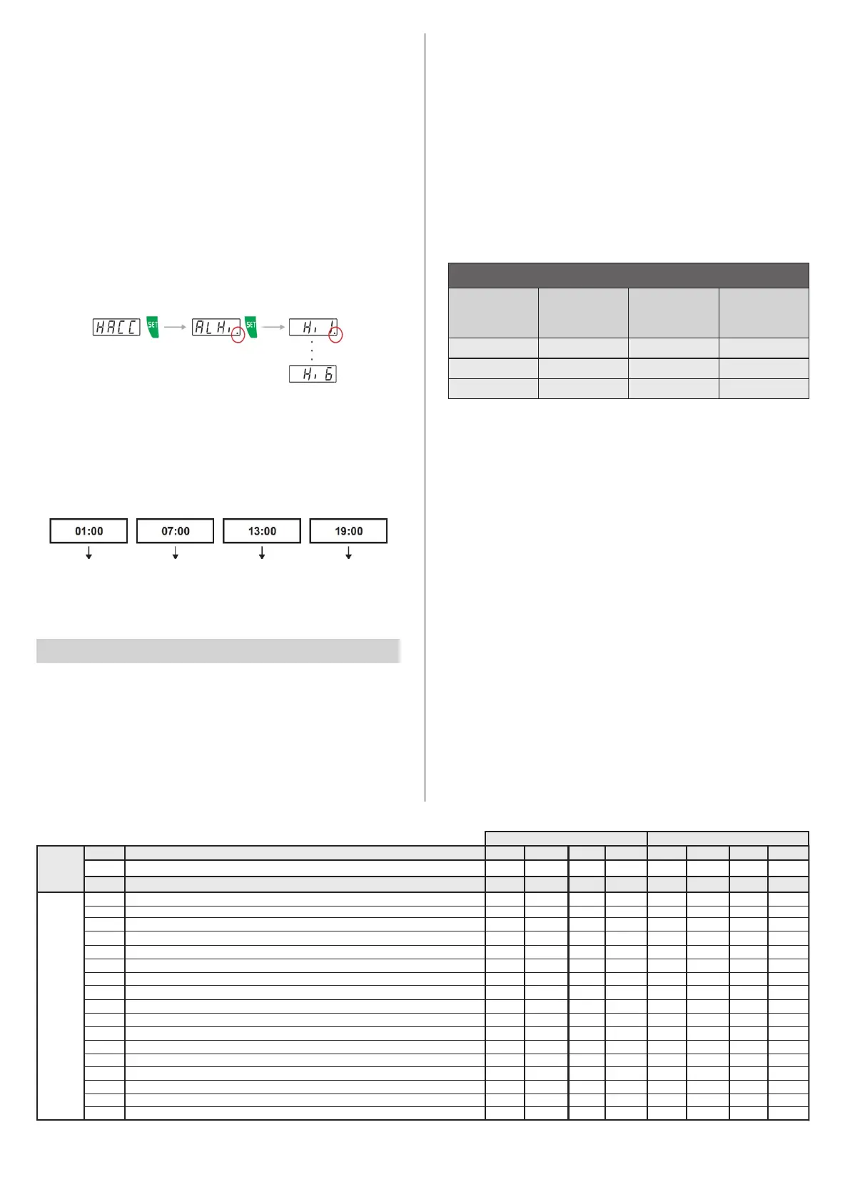
The facilitate viewing of new HACCP alarms, the dot in the lower right corner of the alarm type will be lit,
indicating which alarms have not yet been viewed, as shown in the figure below.
9.4.7 Scheduled Defrosting
You can configure the defrosting schedule to be equally distributed across the day by programming the
number of defrost cycles per day. To do this, you need to set the start of the defrosting as part of a
defrosting schedule, setting [F19] to 5, and configuring functions [F28] to [F37] to determine the
number of defrost cycles per day and their preferred times. With this, the defrost schedule makes it
possible to create a program from Monday to Friday, another program for Saturday and another for
Sunday. E.g. If the program for Monday to Friday consists of a preferred time of 1 pm (and the number of
defrosting cycles is 4, with an interval of 6 hours), the defrost schedule will be operate at 1:00 am, at 7:00
am, at 1:00 pm and 7:00 pm on each day.
9.4.8 Variable compressor control
The control settings of the variable compressor differ depending on the brand and model of the variable
compressor used. Consult the compressor’s technical manual.
In traditional cooling applications, the demand for using the compressor at full load is rare and restricted
to a few days a year. The control of the operating frequency of a variable capacity compressor adapts its
use to the real demand. This way, the compressor runs at a low speed most of the time, minimizing
energy consumption.
The operating frequency is proportional to the cooling capacity defined in parameters [F74] and
[F75]. The parameter [F76] defines the maximum operating frequency of the compressor and is
used in situations where it is needed to quickly lower the temperature of the controlled environment.
It is possible to keep the compressor operating continuously, keeping the temperature of the controlled
environment stable and reducing the number of compressor starts, thereby resulting in energy savings.
To use this characteristic, parameter [F82] - Variable compressor time on after reaching the setpoint
must be programmed.
9.4.9 Control PID
The PID controller is made up of a combination of three control actions: Proportional action (P), Integral
action (I) and Derivatice action (D). Each action receives a weighting (adjustable via parameters)
which represents a gain or adjustment time. This enables the PID to perform better when controlling
the process. Any control action is limited by the quality and capacity of the existing actuators in the
process.
P - Proportional gain (Pg) - The use of proportional action in a control system enables the difference
(error) between the desired output (reference, setpoint) and the current value of the process, to be
reduced. The proportional gain speeds up process’s response, however, the increased gains can
result in control oscillating.
I - Integral time (It) - The integral action has an energy storage function, which allows it to remove the
error between the reference and the output. It accumulates the error at a ‘’It’’ rate and attempts to
reduce it to zero. Low It values can cause the control to oscillate, however, long It times tend to slow
down the process Integral action must not be used on its own.
D - Derivative time (Dt) - The use of derivative action enables the process’s response time to be
increased and reduces oscillation, as it tries to anticipate the process’s behavior. Low values of Dt act
in a way to reduce the oscillatory anticipating the behavior of the process, however, high Dt values will
make the control very reactive, causing instability. Integral action must not be used on its own.
Obs.: Change the parameters individually, check the response and then modify another parameter. Proceed with
caution, to monitor the behavior of the process, analyze and modify the control parameters*. This guide is widely applied
in the technical literature on PID controllers, however processes with latency in their response may differ from the
indication in the table. The technician responsible for the process must correct small deviations manually. ** In specific
applications, the behavior can be reversed to that indicated.
SUMMARY TABLE - GENERAL GUIDANCE*
PID PARAMETER
OVERSHOOT
(peak, sobressinal)
STABILIZATION
TIME
(delay in stabilizing the
controller)
Increase KP**
Increase Little Effect Reduce
Increase Increase Null error
No effectReduce Reduce
Reduce Ti
Increase Td
ERROR
(the difference between
the setpoint and the
sensor)
9.5 Parameters Table
Min
Max
Standard Standard
Unit
Description
Fun
[,F00]
[CODE]
[,F01]
[,F02]
[,F03]
[,F04]
[,F05]
[,F06]
[,F07]
[,F08]
[,F09]
[,F10]
[,F11]
[,F12]
[,F13]
[,F14]
[,F15]
[,F16]
[,F17]
Min
Max
Unit
0
0
2
999
0
0
-9,0
0
0
0
0
2
999
°C
15,8
-
-
-
-
°C
°C
minutes
minutes
minutes
minutes
minutes
[,F04]
[,F04]
[,F04]
[,F04]
[,F04]
°F
°F
°F
[,F03]
[,F03]
[,F03]
-50,0
0,1
0,1
0,1
0,1
[,F03]
[,F03]
-4,0
-11,0
24,8
12,2
[,F04]
[,F04]
[,F03]
[,F03]
°C
°C
°C
°C
105,0
20,0
20,0
20,0
20,0
°C
°C
°C
°C
°F
°F
°F
°F
221,0
°F
°F
°F
°F
36,0
36,0
36,0
36,0
0,1
0,1
0,1
0,1
hh:mm
hh:mm
hh:mm
hh:mm
hh:mm
hh:mm
20,0
20,0
999
999
999
999
999
999
36,0
36,0
24:00(Off)
24:00(Off)
24:00(Off)
24:00(Off)
24:00(Off)
24:00(Off)
24:00(Off)
24:00(Off)
24:00(Off)
24:00(Off)
24:00(Off)
24:00(Off)
105,0
221,0
0,1
0,1
0(Off)
0(Off) 300
0(Off) 0(Off)0(Off)
minutes
0(Off)
0(Off)
0(Off)
-50,0
-58,0
-58,0
[,F04]
[,F03]
3,0
3,0
3,0
3,0
5,4
5,4
5,4
5,4
00:00
00:00
00:00
00:00
00:00
00:00
2,0
5,0
120
120
300
3,6
9,0
0,1
0,1
Controller operating mode
Access code: 123 (one hundred and twenty three)
Setpoint temperature
Desired temperature (economic setpoint)
Minimum desired temperature (setpoint) allowed to the user
Maximum desired temperature (setpoint) allowed to the user
Operating setpoint control differential (cooling)
Economic setpoint control differential (cooling)
Operating setpoint control differential (heating)
Economic setpoint control differential (heating)
Time for economic mode to begin (Monday to Friday)
Time for economic mode to begin (Saturday)
Time for economic mode to begin (Sunday)
Temperature difference (S3-S1) below which the economic setpoint is activated
Temperature difference (S3-S1) above which the economic setpoint is activated
Maximum temperature in economic mode
Fast Freezing temperature limit
Maximum fast freezing time
Delay time when powering up the controller
CELSIUS (°C)
FAHRENHEIT (°F)
COOLING / HEATING
MODO
MONDAY TO FRIDAY
DEFROST DEFROST DEFROST DEFROST
 Loading...