© Fulton Group N.A., Inc. 2022
INSTALLATION EDR-SOLA-IOM-2022-0216 SECTION 2
2-14
any other point may be subject to losses associated
with upstream piping.
Consult the regulator manufacturer for orice selection.
If two or more springs are available for a particular
outlet pressure in the desired range use the spring with
the lower range for better accuracy.
Gas Piping Installation
Field gas piping must be installed in accordance with NFPA
54 National Fuel Gas Code, ANSI Z223.1, and any other local
codes which may apply.
Adhere to the following for gas piping installation:
1. See Table 3 for required natural gas pipe size, based on
overall length of pipe from the meter plus equivalent
length of all ttings. Approximate sizing may be based
on 1,020 BTU for 1 cubic foot of natural gas. See Figures
6 and 7 for piping arrangements.
2. Piping must be of the proper size to ensure adequate
gas supply. It is typical for gas delivery piping to be up-
sized one or several diameters larger than boiler gas
inlet size.
3. The pipe and the ttings used must be new and free of
dirt or other deposits.
4. When making gas-piping joints, use a sealing
compound resistant to the fuel gas serving the boiler.
5. Install a manual gas shuto valve and union (not
supplied) prior to the boiler.
6. Piping must be installed such that no piping stresses
are transmitted to the boiler. The boiler cannot be used
as a pipe anchor.
7. All gas piping connections must be pressure-tested and
checked for leaks before being placed into service. Test
with compressed air or inert gas if possible.
8. The boiler gas train must be disconnected at the boiler
manual shuto valve from the gas supply piping system
during any pressure testing of the system at pressures
in excess of 1.0 psig (28 inch W.C.).
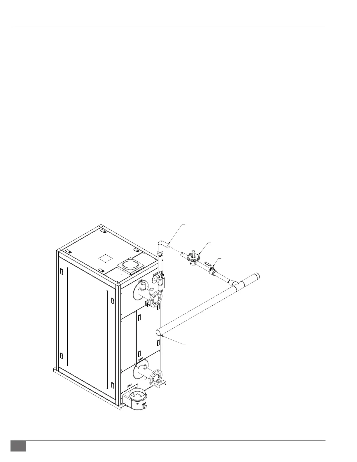
FIGURE 10 ENDURA SINGLE BOILER GAS SUPPLY PIPING
GAS SUPPLY
MANUAL
SHUTOFF VALVE
LINE GAS PRESSURE REGULATOR (SEE NOT
SEE NOTE 2,3
NOTES:
1.
2.
3.
4.
5.
REQUIRED FOR INSTALL
W.C. INLET PRESSURE. F
REQUIRED 10 PIPE DIAM
REGULATOR CONNECTIO
STRAIGHT UNINTERRUP
OUTLET AND ANY FITTI
THE LINE REGULATOR S
MINIMUM OF 10 LINEAR
REG
ULATOR OUTLET AN
THIS DRAWING IS NOT
REFER TO THE INSTALLA
INFORMATION REGARDI
AND OTHER INSTALLATI
Notes:
1. Required for installation with greater than
28”W.C. (14”W.C. Canada) inlet pressure, eld
supplied.
2. Required 10 pipe diameters equivalent to the
regulator connection size. This pipe must be
straight, uninterrupted pipe between regulator
outlet and and any ttings, valves, or elbows.
3. The line regulator should be installed with a
minimum of 10 linear feet of pipe between the
regulator outlet and boiler fuel train inlet.
 Loading...