4-1 A03P3DC
CABINET DISASSEMBLY INSTRUCTIONS
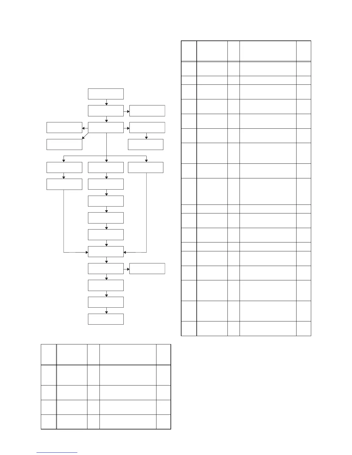
1. Disassembly Flowchart
This flowchart indicates the disassembly steps for the
cabinet parts, and the CBA in order to gain access to
item(s) to be serviced. When reassembling, follow the
steps in reverse order. Bend, route and dress the
cables as they were.
2. Disassembly Method
Step/
Loc.
No.
Part
Fig.
No.
Removal Note
[1]
Stand
Cover
Assembly
D1 6(S-1) ---
[2]
Stand
Hinge
D1 4(S-2), 2(S-3), 2(S-4) ---
[3]
Stand Sub
Cover
D1 --------------- ---
[4]
Rear
Cabinet
D1
20(S-5), 4(S-6),
2(S-7), (S-8), (S-9)
---
[2] Stand Hinge
[4] Rear Cabinet
[6] Speaker
[5] Speaker
Holder
[3] Stand Sub
Cover
[11] Inverter
Power CBA
[15] Shield Box
[17] PCB Holder
[19] Stand
Bracket
[18] AC Inlet
Holder
[14] Jack Holder
[12] Tuner Shield
[9] Jack
Holder(HP)
[10] Jack CBA
[16] Digital Main
CBA Unit
[13] Power
Supply CBA
[21] LCD Module
Assembly
[22] Front
Cabinet
[1] Stand Cover
Assembly
[8] Function
CBA
[7] IR Sensor
CBA
[20] Wall Mount
Bracket (L,R)
[5]
Speaker
Holder
D2
D6
6(S-10), CN801,
CN802
---
[6] Speaker D2 --------------- ---
[7]
IR Sensor
CBA
D2
D6
(S-11), CN101,
CL103A
---
[8]
Function
CBA
D2
D6
Function Knob,
Knob Frame
---
[9]
Jack Holder
(HP)
D3 (S-12) ---
[10] Jack CBA
D3
D6
2(S-13), CL201A ---
[11]
Inverter
Power CBA
D3
D6
4(S-14), CN1801,
CN1810, CN1851,
CN1852
---
[12]
Tun er
Shield
D4 2(S-15) ---
[13]
Power
Supply
CBA
D4
D6
6(S-16), CN401,
CN402, CN403,
CN404, CN452,
CN601
---
[14] Jack Holder D4 2(S-17) ---
[15] Shield Box D4
9(S-18), 2(S-19),
2(H-1), CN3903
---
[16]
Digital Main
CBA Unit
D4
D6
--------------- ---
[17] PCB Holder D4 4(S-20) ---
[18]
AC Inlet
Holder
D5 2(S-21) ---
[19]
Stand
Bracket
D5 4(S-22), 4(S-23) ---
[20]
Wall Mount
Bracket
(L,R)
D5 4(S-24) ---
[21]
LCD
Module
Assembly
D5 3(S-25), 6(S-26) ---
[22]
Front
Cabinet
D5 --------------- ---
↓
(1)
↓
(2)
↓
(3)
↓
(4)
↓
(5)
Step/
Loc.
No.
Part
Fig.
No.
Removal Note