5-3 A03A0EA
The White Balance Adjustment should be
performed when replacing the LCD Panel
or Digital CBA.
4. White Balance Adjustment
[Video/Component/PC]
Purpose: To mix red, green and blue beams correctly
for pure white.
Symptom of Misadjustment: White becomes bluish
or reddish.
1. Operate the unit for more than 20 minutes.
2. [VIDEO input]
Input the White Raster (70%=70IRE,
30%=30IRE).
[Component input]
Input the 720P White Raster (70%=70IRE,
30%=30IRE).
[PC input]
Input the SVGA White Raster (70%=70IRE,
30%=30IRE).
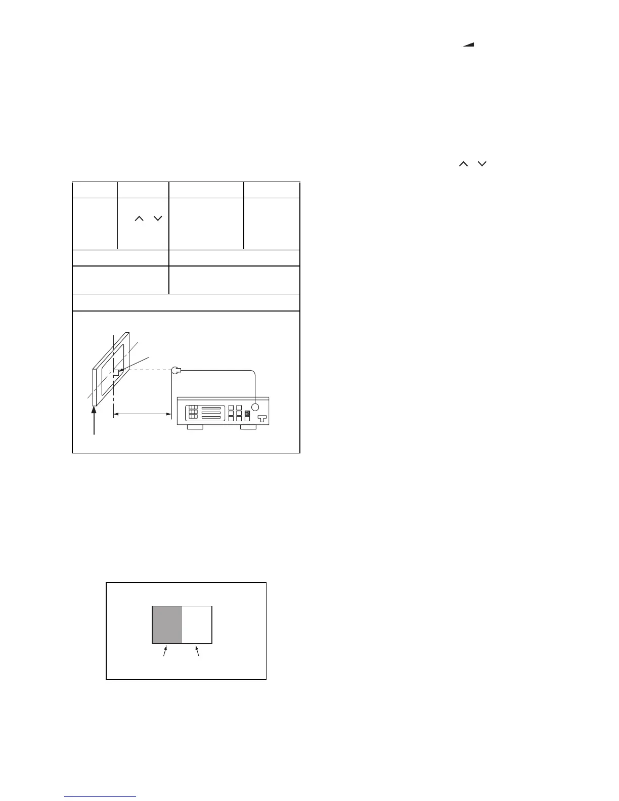
3. Set the color analyzer to the CHROMA mode and
bring the optical receptor to the center on the
LCD-Panel surface after zero point calibration as
shown above.
Note: The optical receptor must be set
perpendicularly to the LCD Panel surface.
4. Enter the Service mode. Press [ -] button on the
service remote control unit and select “C/D” mode.
5. [CUTOFF]
Press [3] button to select “COB” for Blue Cutoff
adjustment. Press [1] button to select “COR” for
Red Cutoff adjustment.
[DRIVE]
Press [6] button to select “DB” for Blue Drive
adjustment. Press [4] button to select “DR” for Red
Drive adjustment.
6. In each color mode, press [P / ] buttons to
adjust the values of color.
7. Adjust Cutoff and Drive so that the color
temperature becomes 9200°K (x
=
0.286 / y
=
0.295
±0.005).
8. Change the video signal input in step 2 and repeat
from step 3.
9. To cancel or to exit from the White Balance
Adjustment, press [BACK] button.
Test Point
Adj. Point Mode Input
Screen
[P / ]
buttons
[VIDEO]
C/D
White Raster
(APL 70%)
or
(APL 30%)
M. EQ. Spec.
Pattern Generator,
Color analyzer
x= 0.286 ± 0.005
y= 0.295 ± 0.005
Figure
Color Analyzer
L = 3 cm
Perpendicularity
INPUT: WHITE 70%, 30%
To avoid interference from ambient
light, this adjustment should be
performed in a dark room.
30%=30IRE
70%=70IRE
INPUT SIGNAL