9-6
A03P3BLP
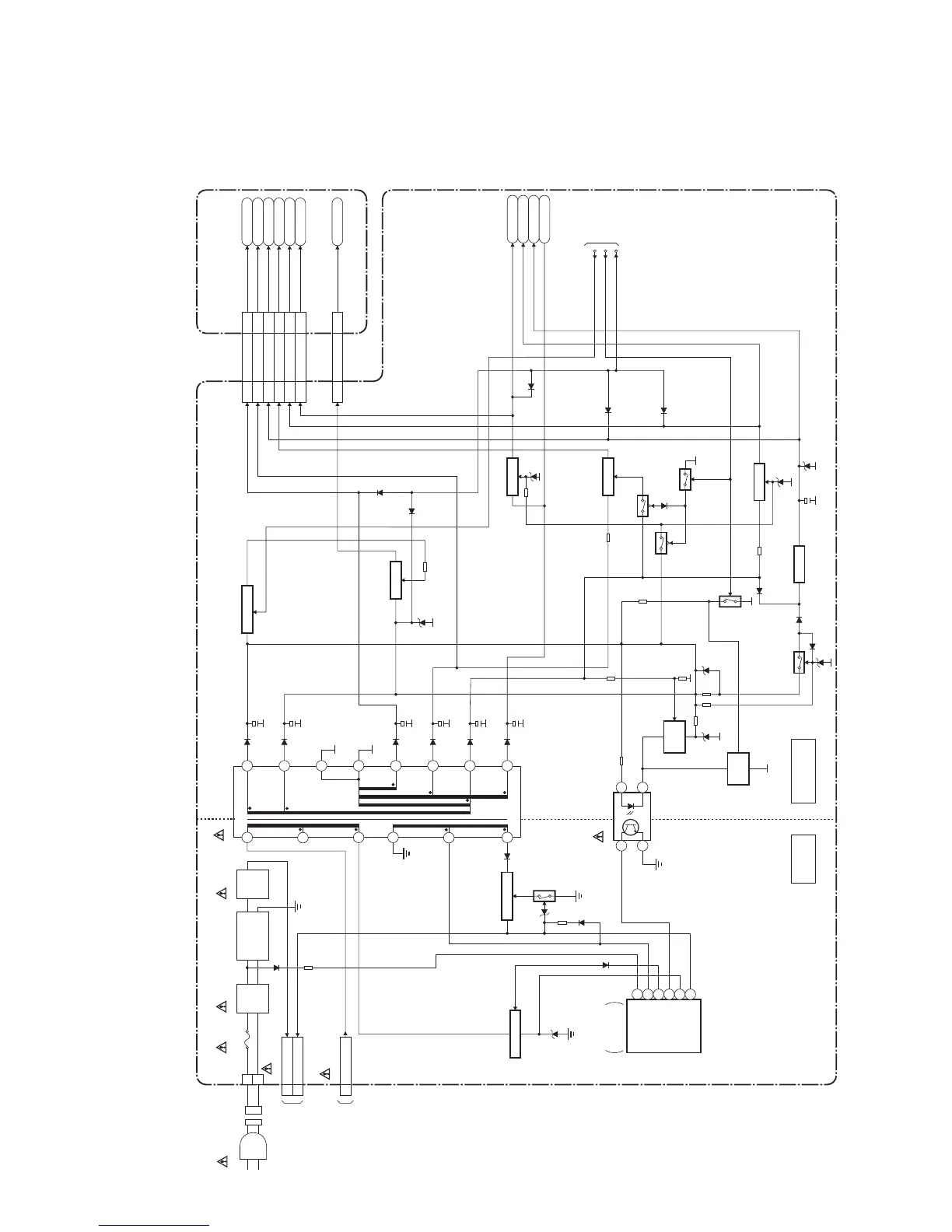
Power Supply Block Diagram
HOT COLD
POWER SUPPLY CBA
HOT CIRCUIT. BE CAREFUL.
14
3 2
IC607
T601
TO INVERTER
POWER BLOCK
DIAGRAM
(CN1810)
CN610
H.V.(BLACK)1
1
2
HOT+15V(RED)
4
H.V.(BLACK)1
LINE
FILTER
L601A, L602A
BRIDGE
RECTIFIER
D609- D612
TO INVERTER
POWER BLOCK
DIAGRAM
(CN1801)
FEED
BACK
FEED
BACK
Q621
SWITCHING
Q512,
Q522
CN402
CN452
CN3701
CN3711
Q504, Q505
SWITCHING
Q516
Q513
Q514
Q623
Q511
Q508
Q518
SW+5V
Q521
Q517
SW+9V
Q501
SW+12V
Q510,D526
SW+3.3V
SW+3.3V
LINE
FILTER
T602F601
T4A H 250V
P-ON-H1
TO SYSTEM
CONTROL
BLOCK
DIAGRAM
P-ON-H2
PROTECT1
Q520
P-ON+5V
AL+3.3V
AL+13V
P-ON+9V
13,14
6
10
27-29
LCD+12V
P-ON+9V
AL+3.3V(1)
AL+5V
AL+3.3V
P-ON+3.3V
P-ON+5V
DIGITAL MAIN CBA UNIT
P-ON+3.3V13,14
P-ON+9V6
2,3
LCD+12V3,4
AL+3.3V10
24,26
19-21
AL+5V24,26
AL+3.3V(1)19-21
P-ON+5V27-29
CN600
CN601
4
2
3
15
9
13
12
14
11
10
16
8
6
7
8
IC621
SWITCHING
CONTROL
VH
1
ZCD
5OUT
2
FB
3
IS
6VCC
Q622
SWITCHING
AC CORD
AC
INLET
NOTE:
The voltage for parts in hot circuit is measured using
hot GND as a common terminal.
CAUTION !
Fixed voltage (or Auto voltage selectable) power supply circuit is used in this unit.
If Main Fuse (F601) is blown , check to see that all components in the power supply
circuit are not defective before you connect the AC plug to the AC power supply.
Otherwise it may cause some components in the power supply circuit to fail.
CAUTION !
For continued protection against fire hazard,
replace only with the same type fuse.