Home
Furuno
Marine Radar
1830
Furuno 1830 User Manual
4
of 1
of 1 rating
66 pages
Give review
Manual
Specs
To Next Page
To Next Page
To Previous Page
To Previous Page
Loading...
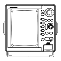
OPERATIONAL
OVERVIEW
THE
FRONT
PANEL
This
radar
is
basically
very
easy
to
operate.
If
you
change
a
control
setting
you
will
see
the
associated
reaction
almost
immediately
on
the
screen.
Most
touchpads
carry
abbreviated
names
to
show
their
functions.
The
same
nomenelalure
appears
on
the
screen
for
confirmation.
Examine
the
Display
Unit.
You
will
notice
that
all
Controls
are
on
the
right-
hand
side.
and
the
CRT
(display
screen)
is
on
the
left-hand
aide.
The
TUNE,
Al
C
SEA,
and
GAIN
Controls
are
grouped
together
because
they
Control
the
radar
receiver.
To
prevent
accidental
alteration
of
the
settings,
all
Controls
in
this
group
may
be
locked
by
pushing
in
the
control.
When
readjustment
is
necessary,
push
in
and
release
the
control
to
bring
it
out
again.
The
and
touchpads
turn
on/off
power
and
transmission.
The
„TlÅllL
touchpads
change
the
range
scale
in
use.
The
[SI.
EOO
and
touchpads
are
mostly
un/uff
coiiiruls.
Adjusting
the
Drightness
ol
the
CRT,
reducing
radar
interference,
and
temporarily
erasing
the
heading
mark
are
some
of
the
functions
of
this
group
of
touchpads.
The
and
1^{
touchpads
are
used
with
the
trackball.
The
trackball,
whose
motion
is
followed
by
an
on-screen
cross
hair
cursor,
is
used
to
set
a
guard
zone
and
measure
a
target's
range
and
bearing.
Maneuver
Uie
cursor
to
an
edge
of
tne
guard
zone,
to
the
bearing
or
lo
the
distance
you
desire,
then
press
one
of
the
above
three
touchpads.
Press
snri
hold
the
jSjjiwEj
to
cancel
each
funetion.
and
touchpads
for
two
to
three
seoonds
To
familiarize
yourself
with
the
Controls
of
your
unit,
turn
it
on
(presuming
that
it
has
already
been
instaUedl
and
try
operating
some
of
the
Controls
as
you
review
this
section.
The
Controls
described
in
"Turning
the
Unit
On
and
Off"
and
"Setting
Up"
appear
in
the
order
they
should
be
operated
when
turning
on
the
radar.
THE
REAR
PANEL
The
hJCANNUn.
switch
is
provided
on
the
rear
panel
to
turn
on/off
the
scanner
radiator.
This
switch
is
usually
left
upward
("ON"
position)
except
for
field
servicing.
When
turning
it
off,
the
radar
stops
transmission
and
the
message
"ST-BY"
(standby)
appears
on
the
screen.
24
27
29
Table of Contents
Table of Contents
3
Installation
10
General Mounting Considerations
10
Detailed Instructions
10
Display Unit Installation
17
Checking the Installation
19
Initial Procedures
20
Relative Bearing Alignhent
20
Sweep Timing Adjustment
22
Preset Gain Adjustment
22
A/C Sea Adjustment
23
Magnetron Heater Voltage Adjustment
24
Measurement of Blind Shadow Sectors
24
Operational Overview
28
The Front Panel
28
The Rear Panel
28
Turning the Unit on and off
30
Setting up
30
Reducing or Eliminating Interference
37
Better Distinction of Echoes
38
Setting/Oeleting the Alarm
38
Plotting
41
DISPLAYING Nav Data (OPTION)
42
Application
43
Factors Affecting Minimum Range
43
Factors Affecting Maximum Range
43
Interpreting the Display
45
Position Fixing with Radar
49
Collision Avoioance
51
Aids to Navigation
52
Maintenance
53
General
53
Scanner Unit
63
Display Unit
64
4
Based on 1 rating
Ask a question
Give review
Questions and Answers:
Need help?
Do you have a question about the Furuno 1830 and is the answer not in the manual?
Ask a question
Furuno 1830 Specifications
General
Power Output
4 kW
Interface
NMEA0183
Display Size
10.4 inches
Radar Frequency
9410 MHz
Range Scales
0.125 - 36 NM
Weight (Display Unit)
4.5 kg
Related product manuals
Furuno 1835
129 pages
Furuno 1833
248 pages
Furuno COLOR VIDEO PLOTTER 1833C
251 pages
Furuno 1815
148 pages
Furuno 1823C
260 pages
Furuno 1824C
239 pages
Furuno NAVNET 1824C
240 pages
Furuno MARINE RADAR 1823C
260 pages
Furuno INMARSAT-C FELCOM 18
179 pages
Furuno 1715
44 pages
Furuno FAR-1513
198 pages
Furuno FAR-1416
226 pages
 Loading...