3. INITIAL SETTINGS
3-9
• If the equipment is connected as shown in the figure below, change the time lag set-
tings as indicated.
• If the connection is different from those mentioned here, calculate the time lag for
each sensor and enter them accordingly, using the following formula.
Time lag = Transmission delay + Propagation delay
Transmission delay: Delay required for calculation and output by the motion sen-
sor, heading sensor, and position sensor.
SC-30: Use 5 msec for the calculation.
PG-700: Use 50 msec for the calculation.
GP-330B: Use 50 msec for the calculation.
Propagation delay: Time required for the data to reach the DFF-3D, via repeater
and data route. For the multi function display connected by CAN bus, use 15 msec
for the calculation. If NMEA data is fed to the DFF-3D via the NMEA Data Converter
(IF-NMEA2K2), set the calculation figure according to the baud rate between the
sensor and the IF-NMEA2K2 as shown below.
38400 bps: Use 40 msec for the calculation.
4800 bps: Use 145 msec for the calculation.
For example, the sensor feeding data to the multi function display via the IF-
NMEA2K2 has a transmission delay of 30 msec and a baud rate of 38400 bps.
Then, the time lag would be as shown in the calculation below.
Time lag 70 msec = Transmission delay 30 msec + Propagation delay 40 msec
Heading sensor time lag: 65 msec
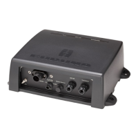
DFF-3D
PG-700 (Motion data and heading data)
------------------
Ethernet CAN bus
------------------
Motion sensor time lag: 65 msec
Position sensor time lag: 65 msec
-----------
㻂
㻂
GP-330B (Position data)
Multi Function
Display