17
3.3 Input of Gyrocompass Signal
If the gyrocompass has no HDT signal, the AD-10 format (FURUNO format) signal
can be input via the FURUNO A/D Converter AD-100. Connect the AD-100 to the
“AD-10 IN” port (D-sub 9 pin) on the rear panel of the transponder unit.
DATA-H
DATA-L
CLOCK-H
CLOCK-L
GND
F.GND
AD-10 IN
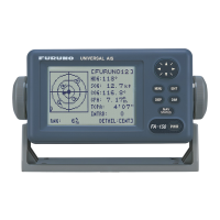
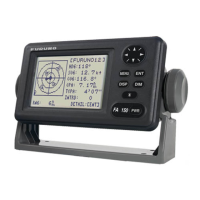
FA-100
>1>
>2>
>3>
>4>
>8>
>9>
Twisted pair cable (Example: TTYCS-1Q cable)
to DATA terminal of AD-100
Note: Set data output interval for 200 ms (instead of 25 ms) by internal jumper
inside the AD-100.
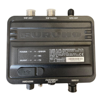
3.4 Alarm Signal Output
The FA-100 generates an alarm signal (relay contact signal) for hardware failure
such as transmitter block or sensor abnormality. For details of alarm type, see the
operator’s manual.
Two kinds of contact signals, on (normal closure) or off (normal open), are output,
and are selected at the junction box CB-100 according to the alarm generator
connected. The maximum current and voltage of the contact are 1 A, 125 VAC and
60 VDC. Normally connect to the NC (normal close) between #46 and #47.
45AOL
46AOH
47AOC
TB-1inthejunctionbox
#45-#47:NormalOpen
#46-#47:NormalClose
47:commonline

 Loading...