EasyManua.ls Logo

Furuno FE-700 Service Manual

Furuno FE-700
58 pages
To Next Page IconTo Next Page
Page #1 background imageLoading...
Page #1 background image
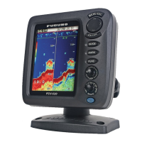
ECHO SOUNDER
MODEL
FE-700

Other manuals for Furuno FE-700

Questions and Answers:

Furuno FE-700 Specifications

General IconGeneral
Frequency50/200 kHz
Power Supply12-24 VDC
Operating Temperature-15°C to +55°C
Display TypeColor LCD
InterfaceNMEA 0183

Summary

System Overview

System Configuration

Overview of the FE-700 system components and their interconnections.

Circuit Description

1.1 General Block Diagram

High-level block diagram illustrating the FE-700's main functional units and data flow.

1.3 Power Supply

Explanation of the FE-700's power supply system, including AC/DC conversion and voltage regulation.

1.4 Transmission Circuit

Description of the circuit responsible for transmitting sonar signals at 50/200 kHz frequencies.

1.5 Receiving Circuit

Details of the circuit that amplifies and processes received sonar signals from transducers.

Troubleshooting

3.1 Diagnostic Test

Guide to performing self-tests for ROM, DRAM, SRAM, battery, keys, and display patterns.

3.3 Alarm and Error Message

Explains common alarm messages like "LOW BATTERY ALARM" and error messages like "EPFS ERROR".

Digital Interface (IEC 61162-1)

Interconnection Diagrams

Interconnection Diagram

Shows how the FE-700 Display Unit, Distribution Box, and other peripherals are connected.

Related product manuals