Do you have a question about the Furuno FEA-2807 and is the answer not in the manual?
Provides an overview of the manual's sections, covering system configuration, operations, chart management, and safety features.
Details the components of the ECDIS workstation and typical network configurations for single and multiple workstations.
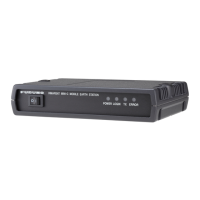
Describes the central unit responsible for chart storage, updating, and processing, including its drives.
Explains the procedure for powering the system on and off, including important notes on connections and initial display.
Outlines the four basic tasks of navigation: Voyage Planning, Positioning, Monitoring, and Steering.
Covers the preparation phase for a voyage, including route definition, calculation, and chart preparation.
Explains how the system calculates and maintains the ship's position using navigation sensors and Kalman filtering.
Describes the continuous checking of navigation data, operator actions, and system performance, including chart display.
Details the ECDIS screen layout, including status bar, information areas, mouse functions, and chart area.
Explains the types of electronic navigational charts (S57, ARCS, CM-ENC) displayed and the information available.
Defines the areas outside the chart display, covering information on settings, parameters, and selections.
Lists available color palettes for chart background and information areas to enhance visibility and distinguish data.
Describes how operators control the ECDIS using the Control Unit (RCU-018 or RCU-015) with trackball and mouse.
Details the RCU-018, including its keyboard, trackball, scrollwheel, and mouse button functions.
Provides a table explaining the function of each key and control on the RCU-018.
Explains the use of hot keys (F1-F4) for quick access to functions or menus.
Guides on updating chart material, displaying/approving dates, and creating/updating user charts and notes.
Details the process of creating new routes or updating existing ones, including route planning and checking.
Explains how to select navigation sensors for use and view their current values.
Describes the importance of datum selection for consistent positioning and chart display alignment.
Introduces vector chart coding techniques, S57, ENC, NON-ENC, and CM-93 formats.
Explains compatibility with IHO S57 release 3, ENC, SENC conversion, and date dependency features.
Provides procedures for loading S57 charts from various media (CD-ROM, USB, LAN) and handling non-compliant charts.
Details the SENC conversion process, including speeding up conversion and automatic settings.
Describes ARCS charts as digital reproductions of Admiralty paper charts, including their availability and update service.
Explains the difference between ARCS chart local datum and WGS-84 datum, and how WGS shift is indicated.
Provides an overview of the Chart menu features for managing charts.
Guides users on obtaining and loading ARCS permits and starting chart operations.
Explains the requirement for mariners to keep charts up-to-date and the role of manual updates.
Describes the use of True symbols and conspicuous orange symbols for manual updates.
Details the editor for manual updates using orange symbols, including planning and editing objects.
Explains the use of the manual update editor with true symbols for chart features.
Explains how ECDIS detects danger areas and generates alerts based on depth or specified conditions.
Outlines the procedure for setting chart alerts using depth contours and other chart objects.
Details how to include user chart symbols, lines, and areas for chart alert calculation.
Describes how system calculates chart alerts for routes based on channel limits and danger areas.
Defines a route plan, its components, and main functions including waypoint definition and optimization.
Details the main parameters for route planning and the steps to complete route planning.
Provides a step-by-step guide to creating a new route, including waypoint definition and alert setup.
Explains available route optimization strategies (Max Speed, Time Table, Max Profit, Min Cost).
Explains route monitoring as a means for permanent ship behavior check relative to the monitored route.
Guides on selecting a route for monitoring from the information area.
Describes how to automatically advance to the next waypoint and select a desired To WPT.
Details the Monitor Route dialog box, its reminders, and how it facilitates safe route use.
Defines user charts as simple overlay charts for highlighting safety-related items and activating alerts.
Explains the concept of a user chart point and its role in radar display and chart alert calculation.
Provides detailed steps for creating and modifying user charts, including lines, symbols, areas, and tidals.
Describes how to define points on a user chart, including adding, importing, and deleting points.
Defines Notes as a notebook data file for messages relative to ship position in monitoring mode.
Explains how to prepare Notes, select modes, and ensure Notes are displayed on the electronic chart.
Guides on selecting Notes for use in monitoring mode by placing the cursor and spinning the scrollwheel.
Details how to configure the ECDIS to send Route, User Chart, and Notes to the radar.
Describes the menus for initiating backup and restore functions for hard disk operations and backup devices.
Explains how the system selects corresponding files based on user selection in the Backup & Restore dialog box.
Provides steps to back up files from the hard disk to a floppy disk or USB memory.
Explains how files can be moved between ECDIS workstations connected via LAN.
Describes systems comprised of one or more workstations and the common reference system concept.
Explains how to manage the common reference system, including usage rights and sensor source.
Details how data is shared and harmonized between workstations via the access server.
Explains the different usage rights (Master, Multi/Slave, Plan) that can be set for workstations.
Discusses sensors used for position, their common reference point, and installation parameters.
Guides on selecting navigation sensors and viewing their current values via the Sensors dialog box.
Illustrates how the system selects the position source and explains related alerts and indications.
Describes the system's three positions (System, Primary, Secondary) and their plotting on the ECDIS display.
Details how to set the color and size of TT symbols on the ECDIS display.
Explains how dangerous tracked targets are displayed as blinking red symbols on the ECDIS.
Guides on setting CPA and TCPA limits used by the ECDIS for target management.
Describes how lost tracked targets are indicated and the lost tracked target alarm (buzzer).
Explains AIS transponder connection to ECDIS, target storage, and IMO reporting rates.
Illustrates various AIS symbols used for different target statuses (sleeping, active, dangerous).
Guides on displaying AIS targets on the ECDIS display and filtering options.
Explains how to filter AIS targets based on categories, range, and priority.
Describes the optional radar overlay feature for displaying radar echo images on the ECDIS chart.
Details how to output and display radar overlay on the ECDIS display by selecting modes.
Explains how to select the radar overlay source via LAN or radar overlay card.
Covers controls for adjusting radar image: gain, sea clutter, rain clutter, and video processing.
Explains how ECDIS records voyage-related items like ship movement, position, and radar targets into logs.
Describes how to access and use Events and Man Overboard (MOB) functions for recording.
Details the voyage information recorded in the Details log, captured once per minute.
Explains the data recorded in the voyage log for the entire voyage, including course, speed, and events.
Describes the anchor watch feature to check ship drifting and set alerts.
Provides steps to activate the anchor watch, including setting drag circle and starting the watch.
Explains the procedure to stop the anchor watch feature and return to normal operation.
Defines datum as a mathematical model of the earth and explains potential errors due to datum differences.
Discusses traditional national datums used in paper charts and compatibility issues with electronic charts.
Explains that electronic sea charts are based on rasterizing or vectorizing paper charts, with exceptions.
Details how true ECDIS uses WGS-84 datum and the requirements for positioning devices.
Covers installation, navigation, and optimization parameters that define system configuration and operations.
Explains menus related to parameters, including how to set time.
Details ship and route parameters crucial for correct integrated navigation system function.
Explains how to set forwarding distances for autopilot steering modes (Go To Track, Go To WPT).
Covers settings for color calibration, including brilliance control and color tests.
Provides a tool to check clear visibility of chart details and distinguish individual colors.
Describes the color differentiation test diagram for checking proper color display of S57 charts.
Explains the use of the gray scale test to visually inspect neutral shades of grey for brilliance and contrast.
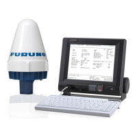
Details how ECDIS receives data from sensors, performs calculations, and displays results on the conning display.
Explains the data displayed on the conning display, received from various sensors like position, wind, and gyro.
Monitors actual Rate of Turn (ROT) displayed in digital and analog formats.
Shows the gyro course in digital and analog formats, with graphical heading representation.
Explains that FEA-2x07 is designed to meet IMO requirements, categorizing alerts by priority.
Describes how alerts are displayed and acknowledged, and mentions three kinds of alerts generated by ECDIS.
Lists alerts generated by navigation calculation, including sensor errors and radar communication issues.
Explains the alert priority system (1-2 for alarms, 3-6 for warnings, 7 for cautions) and syntax.
Provides essential regular maintenance procedures for optimum performance, including checks and cleaning.
Details the procedure for replacing the 5A fuse located at the back of the processor unit.
Explains the procedure for replacing the lithium battery in the CPU board when voltage is low.
Provides a table of common faults and remedies to restore normal operation, emphasizing no operator-serviceable parts.
Illustrates and describes various symbols used in S57 charts, including own ship, radar, and navigation marks.
Provides examples of symbology for ECDIS charts, covering chart data, land features, and soundings.
Illustrates various nature and man-made features as depicted on ECDIS charts.
Shows examples of port features such as shorelines, breakwaters, and lock gates.
Illustrates depth contours, tidal streams, and seabed information.
Introduces the C-MAP CM-93/3 database, its compliance with S57 specifications, and registration requirements.
Details C-MAP services: CM-ENC, Global Chart Database, and SENC delivery.
Explains the priority order for displaying CM93/3 charts with ENC and CM93/2 charts.
Introduces CM93/3 charts as vector charts displayed with ENC and CM93/2 charts.
Describes CM-MAP CM-93/2 charts compatibility, encryption, and authorization code requirements.
Covers licensing system, getting started, keeping charts up-to-date, and defining subscriptions.
Explains the C-MAP licensing system based on serial numbered CD-ROMs and authorization codes.
Provides instructions for loading C-MAP charts from a CD-ROM using the catalogue.
Details saving and restoring route information in ASCII text file format for external applications.
Guides on exporting waypoints' names and coordinates to a Microsoft Excel table.
Explains how to import waypoints' names and coordinates from an Excel table into ECDIS.
Describes backing up and restoring routes in Orion Pro Weather Route Format for program compatibility.
Lists input and output sentences for data communication, including baud rate and parity settings.
Provides a list of valid input sentences for the ECDIS.
Details the structure of input sentences like ACK, ALR, and DBT, including data fields and checksums.
Describes the serial interface, including input ports (Log, Wind, Depth) and output ports (TD-A, TD-B).
Lists all consumable parts for the processor unit, control units, and monitor units with their types and expected life.
Provides diagrams showing the location of components within the chart processor unit, control units, and monitor units.
Details the location of internal components within the EC-1000C chart processor unit.
Shows the internal components and their locations within the RCU-018 control unit.
Introduces the Admiralty Information Overlay (AIO) as a digital dataset for additional navigational information.
Guides on obtaining and installing AIO permits and data to unlock overlay features.
Explains how to enable or disable the AIO display and check the visibility of AIO objects.
Provides examples of Temporary and Preliminary Notice to Mariners (T&P NMs) and EP NMs displayed on AIO.
Describes the ECDIS design standards, components, and its role in navigation assistance.
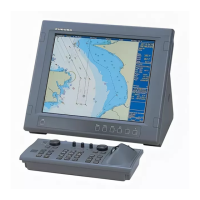
Details the types, pixels, and video input specifications for the ECDIS display units.
Lists the chart materials and information displayed, including Own Ship, ARPA Target, and Radar Overlay.
Explains the available display modes: True Motion and Relative Motion, with various orientation options.
| Category | Marine Equipment |
|---|---|
| Operating Temperature | -15°C to +55°C |
| Resolution | 800 x 600 pixels |
| Power Supply | 12/24 V DC |
| Frequency | 50 kHz / 200 kHz |
| Power Output | 600 W |
| Waterproof Rating | IP55 |