1
1. MOUNTING THE UNIT
NOTICE
Do not apply paint, anti-corrosive
sealant or contact spray to coating or
plastic parts of the equipment.
Those items contain organic solvents that
can damage coating and plastic parts,
especially plastic connectors.
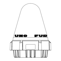
1.1 Antenna Unit
Mounting Location
• There should be no interfering object within the line-of-sight to the satellite. Objects within
line-of-sight to a satellite, for example, a mast may block transmission/reception. Mount
the antenna unit as high as possible. This keeps it free of interfering objects and water
spray. The location should be well away from a GPS antenna. A GPS receiver may be
interfered by the Inmarsat C wave.
• If both Inmarsat-B or F ship earth stations are installed, separate the Inmarsat-B/F
antenna at least 8 m.
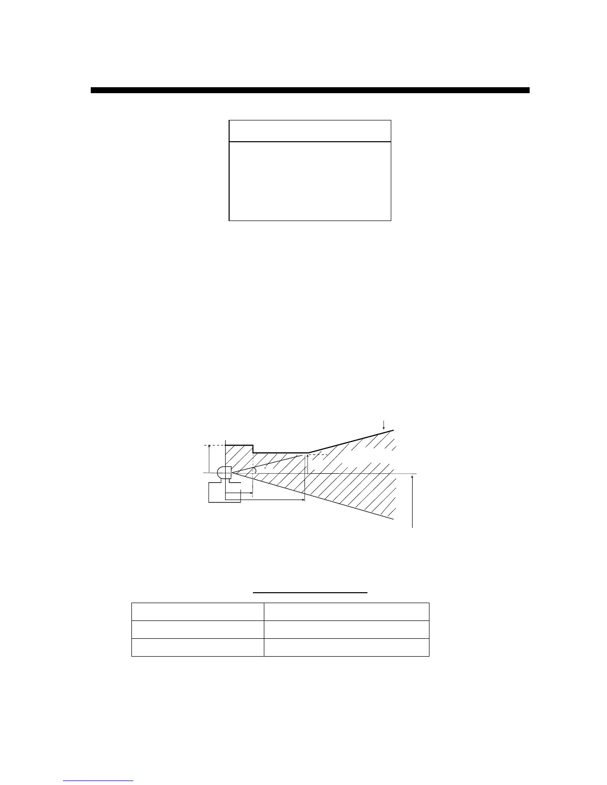
• Separate the antenna unit from an S-band radar as follows:
HORIZONTAL LINE
Install above this line
PROHIBITED
ZONE
1.5 m
5 m
15
2 m
S-band radar
INSTALLTION
ZONE
2 m
S-band radar and installation area
• The allowable vibration level as specified by Inmarsat is as shown in the table below.
Allowable vibration level
Frequency Level
2 to 10 Hz 2.54 mm Peak Amplitude
10 to 100 Hz 9.8 m/s² Peak Acceleration
• Avoid the location near funnels and stacks; smoke and soot on the radome can lower
signal level.
• Separate the antenna unit 5 m from HF, VHF or 27 MHz antenna.
 Loading...