Check List
ii
2. Check of settings
No. Item to be checked Result Refer to
2.1 JP-3 on W/R board (power to the antenna unit, Default: OFF) Page 3-34
2.2
DIP switch setting on T-CPU board for the connection of GNSS,
incoming indicator and distress alert button.
Page 3-29
2.3 Check registered MMSI in DSC Setup display.
Page 3-1
Page 3-27
2.4
Model, FS-1570 or FS-2570 is selected through the menu. Power
data and contents of RT self test differ between two models.
Page 3-2
2.5
The RT is set through Setup menu.
TX FREQ is set in accordance with local regulation.
Page 3-4
Page 3-8
2.6
“SYSTEM” setting of DSC Setup menu is made.
WATCH RCVR is set to HF for the ship navigating in the sea area
A3.
Page 3-14
Page 3-25
2.7
NBDP terminal is setup through the menu, and AAB and ID are
registered. “Slave Delay” of System ([F6]) menu is set to 8 msec.
Page 3-37
MMSI and model registration
1. Press NMI SW (S1) on T-CPU board and enter the password.
2. Select “ALL Clear” and the press [ENT].
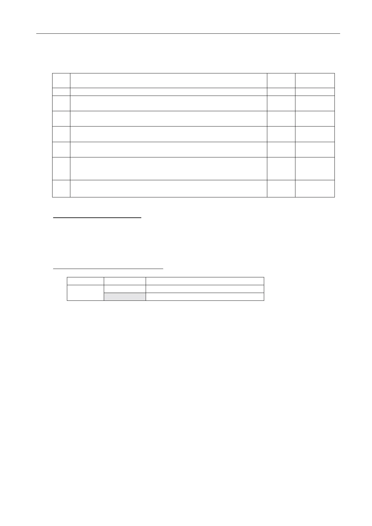
JP-3 setting on W/R-1 and 2 boards
Jumper Remarks
1-2 12 V to FAX-5
JP-3
2-3 No power to antenna (Factory setting)

 Loading...


