14
2.2 Display Control Unit Wiring
Connect the MOD-WPAS0001-030+ cable (from the processor unit) to the LAN connector at the
rear of the display control unit. This cable has 3 m in length. If you need longer cable, use the op-
tional joint box TL-CAT-012 and cable assy MOD-Z072 cable (2, 5 or 10 m). For DCU12, the con-
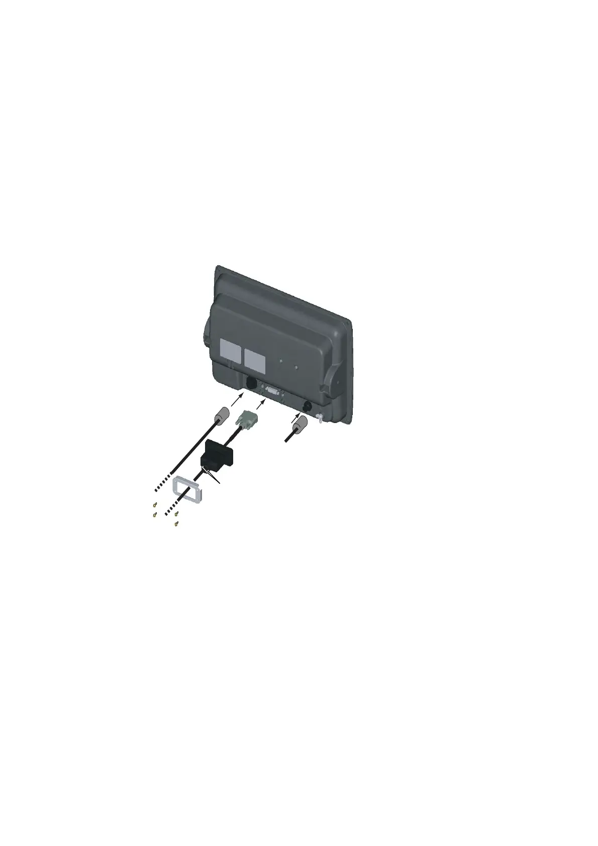
nection of DVI cable is also necessary. When connecting this cable, follow the steps shown below
for waterproofing.
1. Pass the DVI cable through the DVI cover (supplied) and fixing plate (supplied) in that order.
2. Attach the DVI cable to the DVI connector at the rear of the DCU12, and then tighten the
thumbscrews on the connector.
3. Slide the DVI cover so that it covers the connector at the rear of the display control unit.
4. Put the fixing plate over the DVI cover, and then fasten it with four binding screws (supplied).
5. Pass the cable tie (supplied) through two holes on the DVI cap, and fasten it tightly.
MCU-002,
rear view
DVI cable
DVI cover
Fixing plate
Binding screw (M3X10)
MOD-WPAS0001-030+
Pass the cable tie through these holes, and fasten tightly.
MJ-A3SPF0013
(power cable)
 Loading...